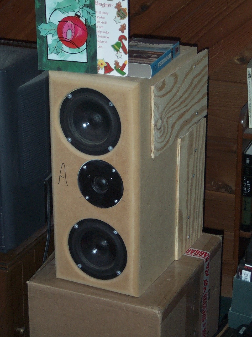
Testing Environment
 |
 |
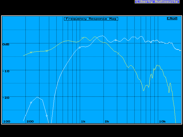
Tweeter and (Combined) Mid-range Responses
Blue Prints of the Cabinet
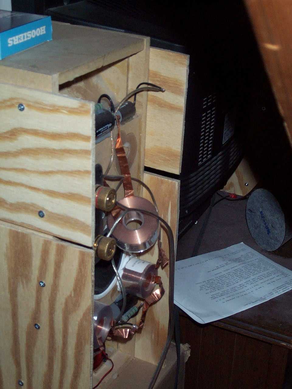
First, I calculated the internal dimensions of the cabinet to see how big the shape I picked would be if it held 18 liters. Notice the two triangular sections… these are where the crossover will go. With separate chambers, the tweeter and woofer crossover components can be physically separated to help prevent electrical interaction.
The dimensions looked Ok. So I placed the drivers on the proposed cabinet front to see how they would fit. Just barely! Notice that the tweeter is placed closer to the upper mid-range. Also, the mid-ranges are going to be recessed by 1/4″, thus a line is drawn to provide the extra space required away from the tweeter. The reflex port has to be on the cabinet’s back behind the tweeter.
 |
 |
Next I looked at where the internal bracing would be positioned relative to the drivers.
The front baffle is double thickness, with additional double thickness behind just the tweeter in order to form a sealed, rear chamber for it. The side-cut is meant to show those pieces bracing the sides. These side-braces are each then braced vertically (not shown).
 |
 |
