Although I made initial tweeter evaluations on large panels, the final speaker design decisions have to take into account the cabinet shape. Why? In the movie Fire Fox Clint Eastwood had to think in Russian. As a speaker builder you have to learn to think in terms of wavelength . One of the audio “rules of thumb” is any object within one wavelength will have an affect on the corresponding frequency range. (However, in my experience, the frequency corresponding to half of a wavelength is more likely to be affected.) The frequency corresponding to a wavelength is computed via
Prototype #1 Description
The design of the this prototype was motivated by the feasable shape that a center channel is allowed. The cabinet pictures with drivers mounted show that this design is pretty similar to many speakers on the market. The cabinet exterior dimensions are 8″ width, 18.5″ height, and 11.5″ depth. The construction material is 3/4″ particleboard (bookshelfs) and is doubled up in the front for the driver baffle. The left and right baffle edges are routed to 1/2″ radius corners. Internal bracing every 4″ is attatched to the sides, top, and back.
| Front View | Side View |
|---|---|
 |
 |
Tweeter positioning tests
These tests were performed without the double (1.5″) front baffle, or any of the internal bracing. The first test was with the tweeter positioned in the center of the baffle.
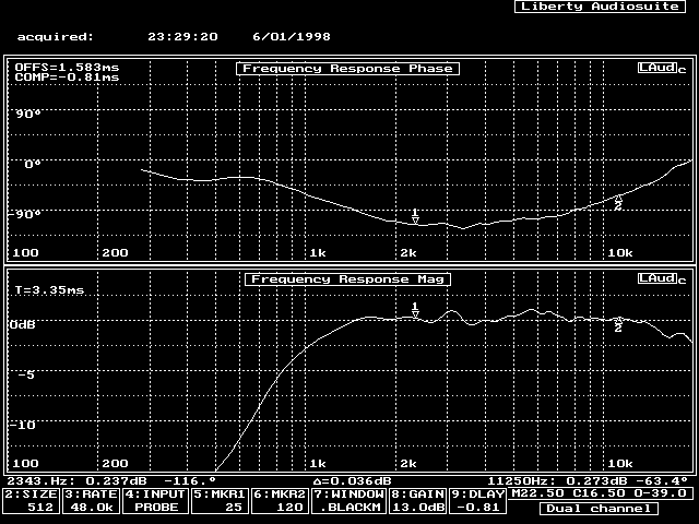
Immediately noticable is the dip between 2.5 and 3.5 kHz.
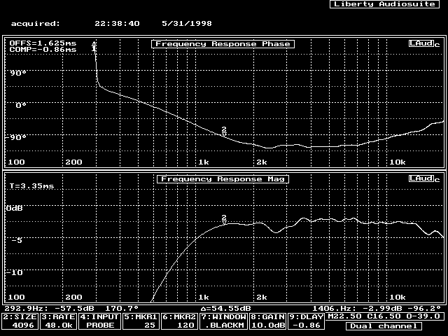
The same measurement with a little longer time window:
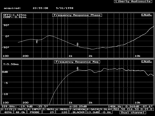
Now, move the tweeter so that the ratio between between the left and right sides is 2 to 1.
However, the definition of the distance to the left and right sides needs some clarification.
First, the edges of the cabinet are rounded, so the “edge” of the cabinet is where? Is it the point on the side where the curve ends? The middle of the corner? The beginning of the corner? Second, should the distance from the edge be measured from the center of the tweeter, or from the edge of the tweeter? I just wish I could remember what I did for this test!
The results of the measurement show that the center of the baffle is not the best location
for a tweeter. The dips in the 2.5 kHz to 3.5 kHz region are now almost gone.
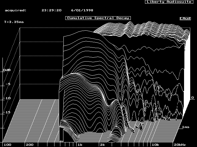
The most prominent anomyly in the response is at 3 kHz. A waterfall plot of this impulse response shows that this frequency has a substantial time span. The wavelength at 3 kHz is 11.5 cm, which does not corrspond to any physical structure, nor does half of this wavelength. But 11.5 cm is for a wave traveling in *air*, not in a solid material. Thus, my conclusion was the peak at 3 kHz was most likely due to a cabinet resonance. Ergo, bracing of the cabinet, even when made out of 3/4″ particle board, was going to be necessary.
Final Raw Driver Measurements
Can’t remember the measurement distance. The mid-ranges are wired in parallel for this test. No data on output signal level. With a time measurement window of 7.3 ms, the response is affected by reflections from within the room (the squiggling on the responses).
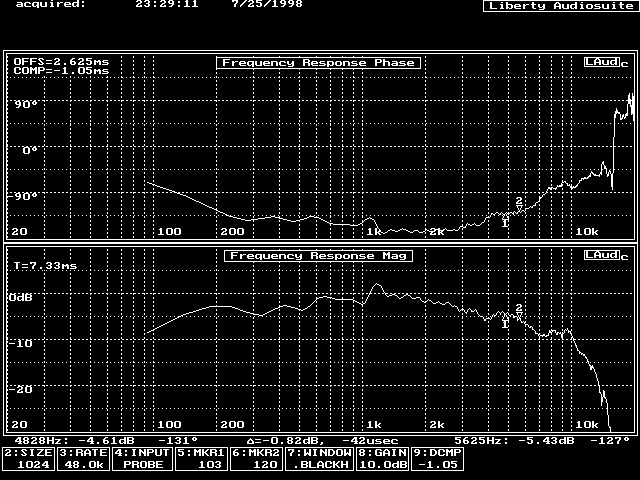
Both response curves show a two major dips in the 2 – 10 Khz frequency range. Further testing is being conducted to locate the source (diffraction, the speaker stand, driver problems, etc.). One area of suspicion is the mid-range; the tweeter positioning tests were made without the mid-ranges present. Consider the table of length-to-frequency conversions:
| Distance | Measurement | Full Wavelength Frequency |
Half Wavelength Frequency |
|---|---|---|---|
| Mid-Range Cone Depth |
1″ | 13.5 Khz | 7.3 kHz |
| Mid-Range Cone Width |
3.5″ | 3.9 Khz | 1.9 Khz |
| Distance from Tweeter to Mid-range Surround |
2″ | 6.8 kHz | 3.4 kHz |
| Distance from Tweeter to Right Edge |
2-3″ | 4.5-6.8 kHz | 2.3-3.4 kHz |
| Distance from Tweeter to Left Edge |
4-5″ | 2.7-3.4 kHz | 1.4-1.7 kHz |
From the dips in the tweeter response, the possible culprits would be the recessed nature of the mid-ranges, and the distance from the tweeter to the mid-range edge. The latter suggests that recessing the mid-range deep enough to “hide” its surround from the tweeter waveform might be desirable.
Copyright © 1998,1999 John Lipp