Speaker III – The Tweeters (Part 2)

morelAs mentioned in earlier tweeter testing , I wanted to revisit some of my tests of the Vifa D27SG-05 and the Morel MDT-30-S. I was suspicious of the foam board introducing measurement anomylies that were not part of the tweeters’ natural responses.

Testing Methodology, Mark II
TweeterTestingII

Testing environment is as before, in the corner of my apartment’s living room. I found some 2’x4’x3/4″ MDF boards at my local Home Depot store.  Since they would fit through the trunk of my BMW M3 (unlike a 4’x 8′ sheet), I bought a pair to make two, dedicated test baffles.  The details:

  • The tweeter locations were 9-1/8″ from the left baffle edge and 18-1/4″ from the top
    baffle edge. That is, the ratios between the top/bottom and left/right edge
    distances as the golden mean, 1.616 to 1.
    I chooose the golden mean since previous tweeter testing with that ratio went well.
  • Each tweeter was recessed so the faceplate was flush with the baffle.
  • The left/right baffle edges (but not the top/bottom edges) were rounded over
    with a 1/2″ radius.
  • Mortite&trade caulk formed the seal between tweeters and baffles.
  • The microphone was at a distance of 18″ from the baffle and at the same height as
    each tweeter. The resulting 3.5ms anechoaic test window yields a lower test
    frequency of 300 Hz.

Caution!

I should mention that MDF has very sharp edges.  Combine this with a large sheet’s weight and a disaster is a possibility.  When handling large sheets, I heartily recommend wearing leather gloves.  For smaller pieces, I would not hold them such that if you loose control, the edge of the board will slide across your hand.  Especially if working the piece with some type of power tool. Ouch!

Test Results

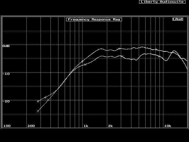
I didn’t have to do too much testing before I was convinced the Vifa tweeter was the better choice for Speaker III.  The first plot is a comparison of the frequency responses of the Vifa (top, flat curve) and Morel (bottom, ugly curve).

compare

The Morel shows two response dips, a narrow dip at about 12 kHz and a wide dip between 3-5 kHz.  The dip at 12 kHz has a corresponding peak at 15 kHz.  This is similar to the foam board test results.

The only anomyly in the Vifa response is a little bit of ripple, most likely from baffle diffraction since the same trends show up in the response of the Morel tweeter as well.  The dips at 7 kHz and 14 kHz in the Vifa foam board tests are now absent.  (Sorry, no comparison plots.)  This suggests the foam board affected the first Vifa tweeter measurements; both samples show no response anomylies on the larger, solid MDF test baffle.  The Morel is a different story; the response dips are similar in the new and the old tests.  I’m a little stumped, and I don’t have a plan yet to become unstumped.

The astute surfer probably has noticed that the Morel response curve is about 2-3 dB lower than the Vifa response curve.  Nothing special is going on; the Vifa is simply a little more efficient than the Morel and has a lower DC resistance (which translates into more power for the same amount of input voltage).

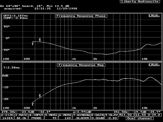
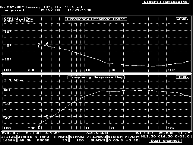
Vifa Magnitude and Phase
vifa
These are impressive plots, as were the corresponding time-domain and waterfall plots.  They should be compared and constrasted with the tests done for prototype cabinet #2 .
Although only just a slightly smaller baffle, prototype cabinet #2 has two mid-ranges mounted in it that definitely affect the frequency response!

There is a downside to the Vifa, however.  The response falls off in the upper octave by 3 dB at 20 kHz.  Fortunately, this can be corrected in a crossover L-pad circuit.

Comparisons with Prototype Cabinet #2

Tweeter test baffle #2 is close in size to the front baffle of prototype cabinet #2.  Yet, the tweeter measurements of prototype #2 show peaks and dips not present in these tests:
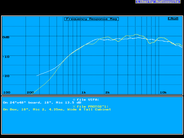
Bare_vs_Proto2

The major difference between these measurements are

  1. Prototype #2 is made from particle board, these test baffles are MDF.
  2. Prototype #2 has two mid-ranges present. Moreover, the mid-ranges are
    equidistant from the tweeter.

I really doubt the first difference is significant.  Thus, I submit that the presence of mid-ranges on the front baffle affects the response more than diffraction in these tests. It makes sense; the mid-ranges are quite a bit closer to the tweeter than the baffle edge.  In fact, I spaced the mid-ranges equidistant from the tweeter.  And I already showed placing the tweeter in the center of a baffle equidistant from the baffle edges was a poor choice.
Ooops!  Cleary some mid-range baffle position experiments are in order for the future.

Morel Magnitude and Phase

morel
Notice the phase shows purtibations corresponding to the peaks and dips in the magnitude of the response.  Not much else need be said.

The Future: Morel Tweaking

I haven’t completely given up on the Morel yet. I started surgery on one of the units.
Testing with the back-chamber (made of plastic, not metal, like the Vifa) removed has demonstrated the shape of and damping material in this chamber noticably affect the response.
Copyright © 1998,1999 John Lipp

Speaker III – Prototype Cabinet #2

Prototype #1 is a rather “typical” enclosure. The front baffle is just wide enough, and tall enough for the drivers and a (future) bass-reflex port. The remainder of the volume is depth.  Anyone can, and it seems everyone does, make a cabinet that simple. But what about a cabinet that is just the opposite? Tall, wide, and just deep enough to form a golden-mean transmission line.

Prototype #2 Description

The cross-sectional dimensions of the golden-mean transmission line are 2-3/4″ deep by 4-1/2″ wide. This width fits perfectly with the Vifa mid-range’s mounting hole diameter. Add a 1-1/2″ double-thickness front and a single-thickness 3/4″ back to the depth generates a total cabinet depth of 5″. But what dimensions for the cabinet front? Well, nothing is wrong with a 1:4:9 ratio, so why not 20″x45″! I had yet to discover medium sized pieces of MDF board at Home Depot (read: pieces of MDF that fit into the trunk of a 3 series BMW). So, to get a 20″ wide face, I glued together two 12″x48″ deep shelf boards. Another shelf board section was glued to the back to get a double baffle where the drivers mount. You can see the sanding marks where the glue edge was smoothed in the front. A few passes with the router set up a 1/4″ deep labyrinth for the walls that would define the rear chambers for each mid-range.  I wasn’t working towards testing a transmission line yet so I made these chambers 4 liters, stuffed with some spare wool, and sealed.


Front Inside Back
proto2_front proto2_inside proto2_back


Narrow & Tall vs. Wide & Deep Cabinet

Having two cabinets with opposite shapes begs the question: what will the differences in driver responses be? My expectation was to see much less ripple in the responses measured on the wide and tall baffle, especially in the upper mid-range. The differences I found, however, were not that significant.

General Testing Conditions

As usual, testing was done in a section of my living room that I have freed up of clutter and furniture. To get a clean measurement, the microphone distance was 18″. As shown in the front picture above, the measurement position is just in front of my washer/dryer closet. For some of the tests Speaker II is used as a stand to raise the driver level and thereby increase the measurement window length.

I also (finally) took the time to learn how to save response data in LAud™ and then display multiple measurement records on the same plot. Thus, most graphs are comparisons of some sort.

Tweeter Tests

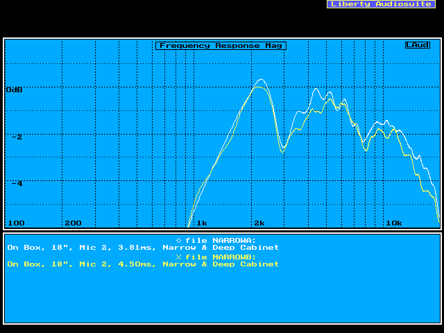
The acoustic diffraction induced response anomylies I was expecting didn’t show up at all!
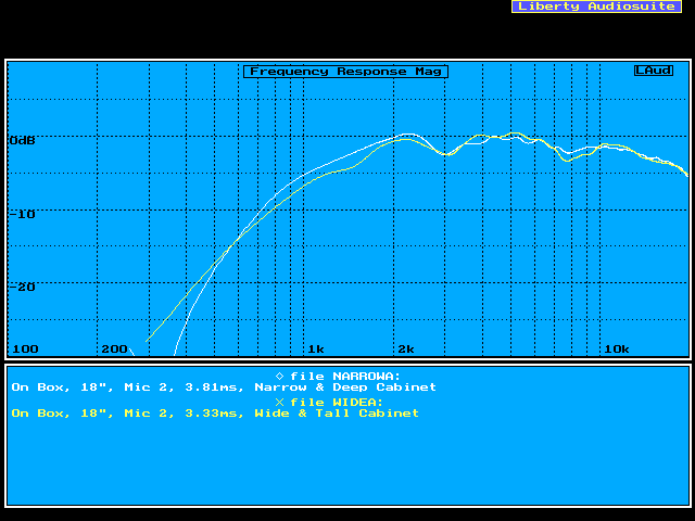
At this point I was rather perplexed. The first thought that came to mind was that the tweeters in each prototype cabinet are different. Thus, I swapped the tweeters between the narrow and wide cabinets. I had to be sure that what I was measuring was not a variation in tweeter units. Take a look at tweeter unit “A” measured in each prototype cabinet:

CompareTwtrA

There is not a whole lot of difference! I was expecting much more of a delta between these two measurements. The diffraction theory I had been reading strongly suggested

  • The response dips and peaks would be at different frequencies, and
  • The magnitude of the dips and peaks would be at least 3 dB less on the wide cabinet.

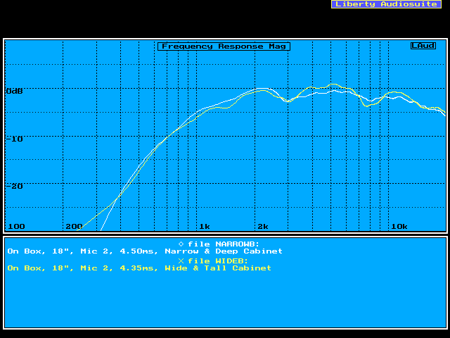
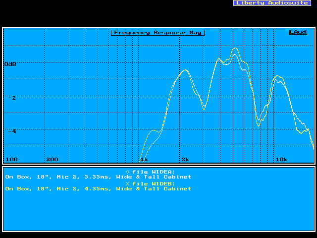
If anything, it appears that the wide & tall cabinet has more pronounced dips in the response. Compare this to tweeter unit “B”:

CompareTwtrB

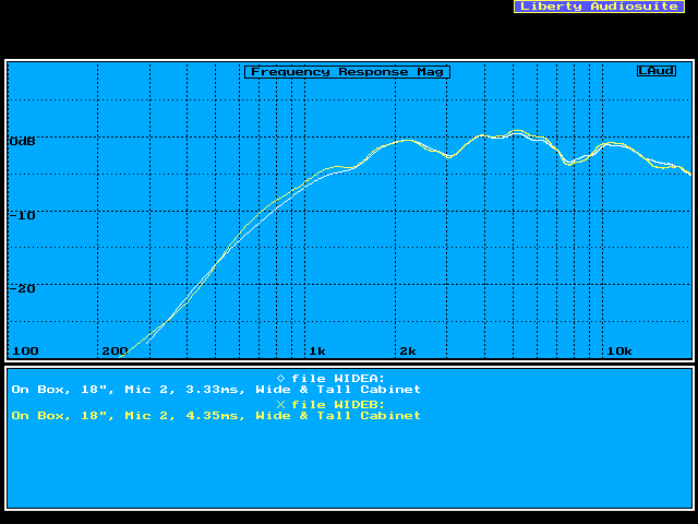
The trends are the same. Hmmmmm… next question… how well matched are the two Vifa tweeter samples? Tweeters A and B on the wide & tall baffle:

WideTwtrAB

As you can see, the match is quite good. Keep in mind that these units are not a matched pair! (They are probably from the same lot.) Now expand the graph’s y-scaling to see just how closely the units match (both baffles shown):

NarrowTwtrAB2

WideTwtrAB2

I would say the quality of matching is about +/- 0.5 dB. Both Morel and Dynaudio charge $$$ for this, but with Vifa you get it for free!

Mid-range Tests

Testing the mid-ranges proved more difficult than the tweeters.

  • I couldn’t test the top and bottom mid-ranges independently and do a comparison between the wide & tall and narrow & deep baffles. Why? The mid-ranges in prototype #1 share a common enclosure while those of prototype #2 each have separate enclosures. That is, if only one mid-range is connected in prototype #1, the other mid-range acts as a passive radiator. That changes the bass response, and possibly affects hi-frequency measurements too.
  • Guaging baffle diffraction correctly for these tests requires measurements below 100 Hz. The long time measurement this requires will include a strong floor reflection, a.k.a., floor-bounce. Floor-bounce commonly manafests itself as a dip in the mid-bass region somewhere between 200 – 400 Hz. This dip is sometimes also accompanied by a peak of 3 – 6 dB at about double the dip’s frequency.

The first issue required connecting the mid-ranges together and carefully positioning the microphone the same distance from each mid-range dust cap. Speaker II was used as a stand for prototype #1, then turned on its side as a stand to raise prototype #2’s driver heights. That I figured would minimize the floor reflection as much as possible. In addition, the mid-range plots were all smoothed in order to reduce “reflection noise.”

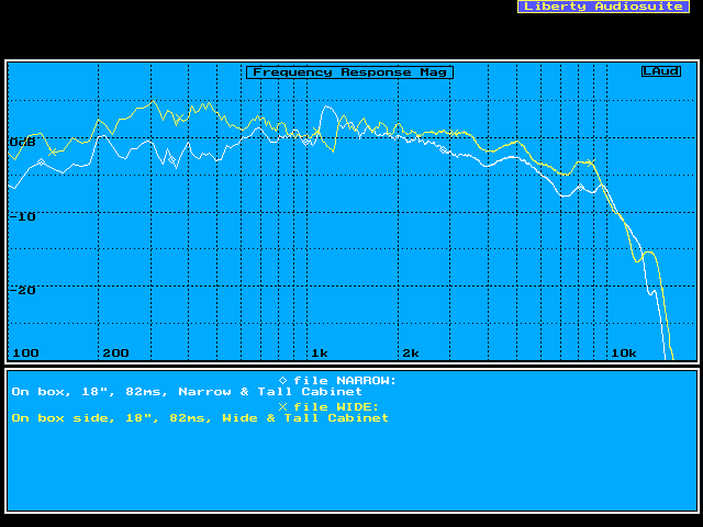
Here is the graph comparing the narrow & deep cabinet with the wide & tall cabinet. This plot has 1/12th octave smoothing:

CompareMids_12th

Most of the small dips and peaks are found in both measurements, especially in the high frequencies. The primary difference is in the lower mid-bass. There, the large baffle has substantially more response. The next plot is smoothed with a 1/3rd octave filter to help to illuminate the general trends in the response curve:

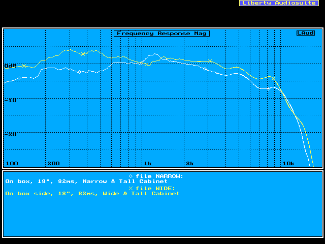
CompareMids

The general impression is that the mid-range drivers in the wide & tall baffle are more efficient. This is as it should be; the mid-bass region should be lifted up because the diffraction frequency is lowered from about 700 Hz to 150 Hz. It also does appear that this Vifa mid-range’s response has been designed to be flat on a “typical,” narrow baffle.

30 degree Off-axis Mid-range Tests

Having established that the mid-bass is lifted by a wider baffle, the next step was examining effects of a wider baffle on off-axis response.

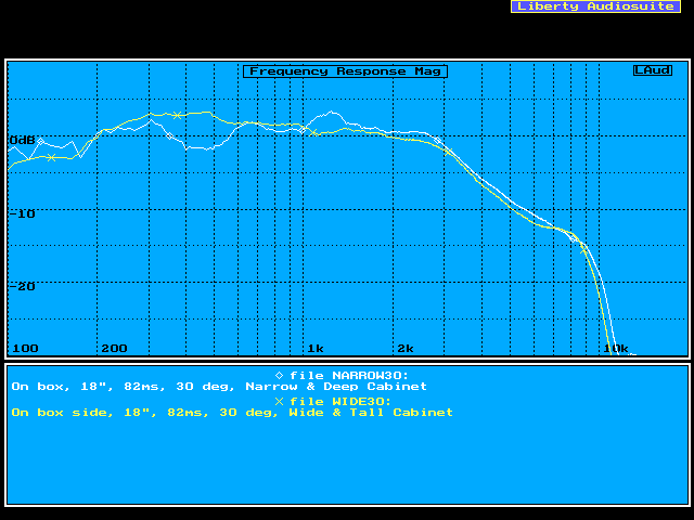
CompareMids30

It appears that the hi-frequency response roll-offs are the same for the wide & tall and narrow & deep enclosures. Question answered. The final two graphs compare the on- and off-axis response of the prototype cabinets to themselves.

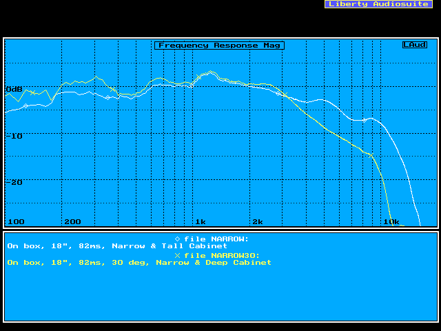
NarrowMids30
The measurements don’t compare too well, but the on- and off-axis responses separate starting at 3 kHz for the narrow enclosure.

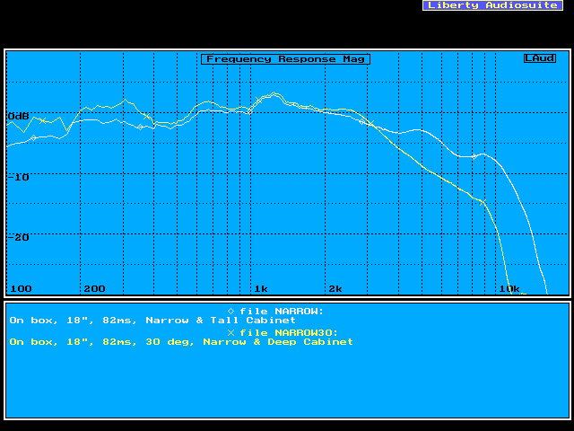
NarrowMids30

The wide enclosure measurements are better behaved. The separation of the on- and off-axis responses is again 3 kHz. However, the 2-3 kHz range has a little more seperation, but I doubt it is significant.

Conclusions

Prototype #2’s test results really surprised me. Now its time to put it all into perspective.
The diffraction effects I was expecting to measure did not materialize. I have a few candidate reasons as to why:

  • The measurement distance of 18″ was “too close” in the sense of near-field vs. far-field.
  • The 1/2″ radius on the edges was sufficient to eliminate the diffraction, especially at the high frequencies.
  • Recessing of the driver’s isn’t taken into account by diffraction theory. (The soft dome of the Vifa tweeter is recessed below the face plate.)

Copyright © 1999 John Lipp