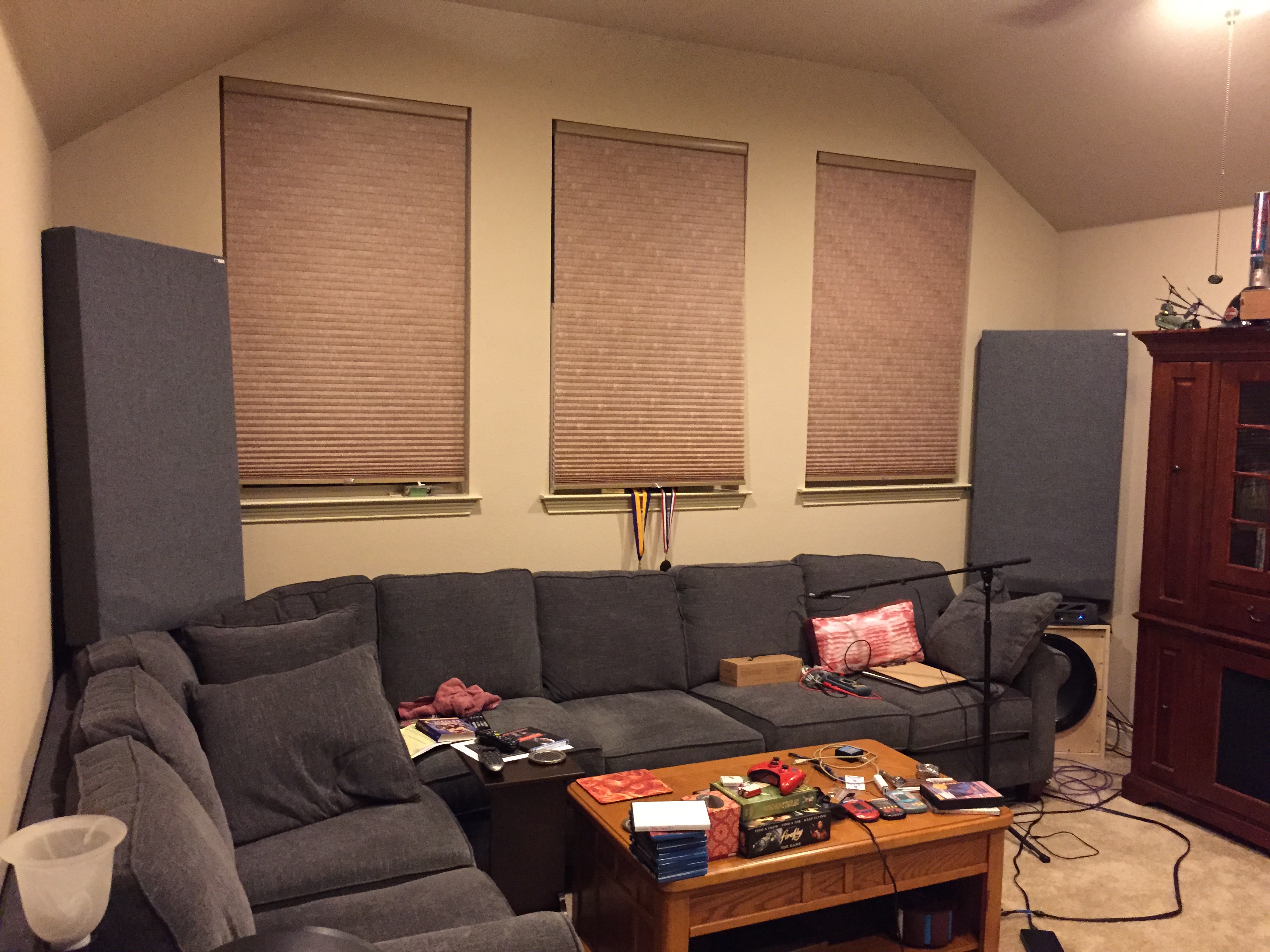
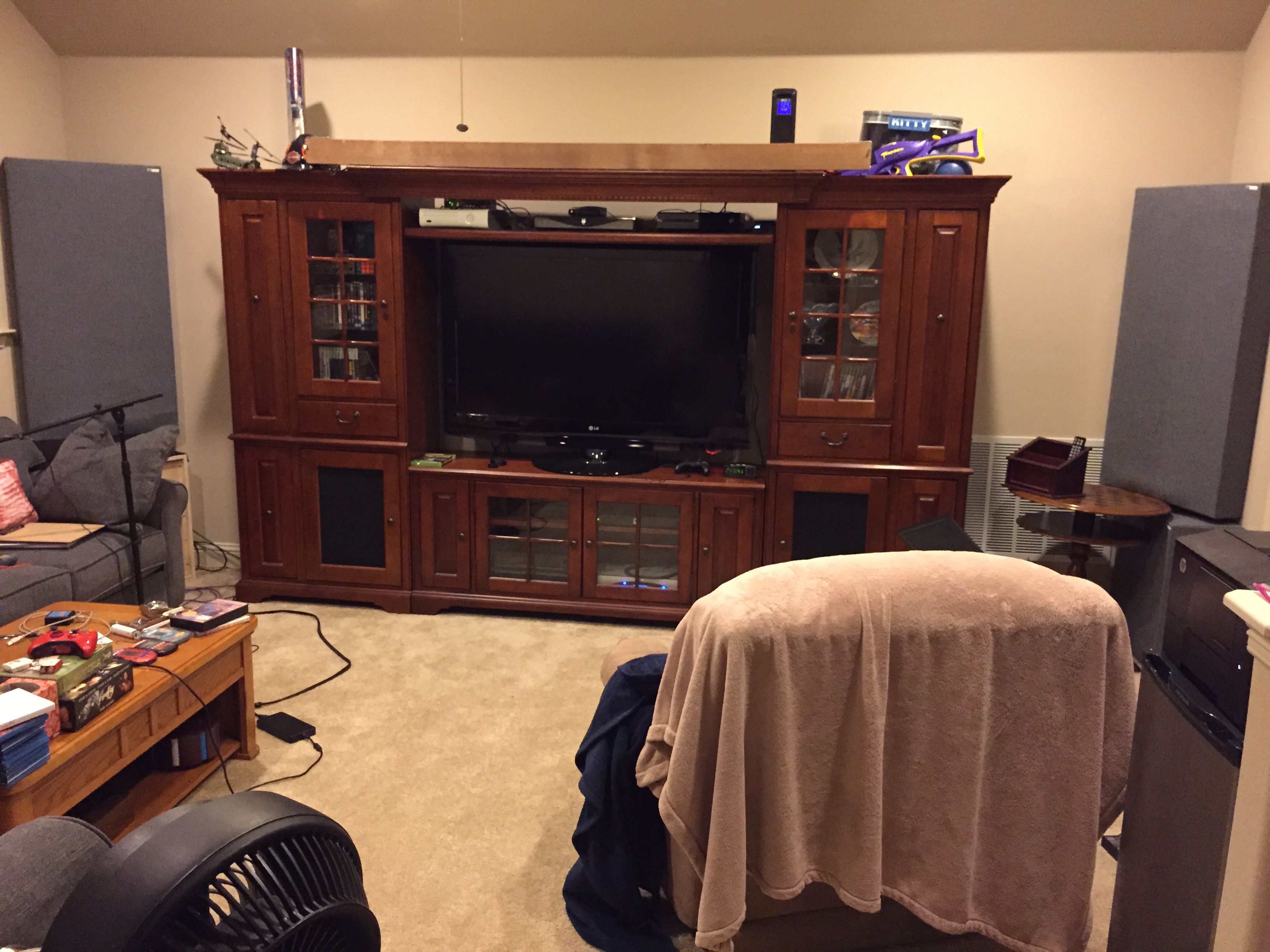
In this installment of Unbaffled, I test three different dipole low-frequency configurations.
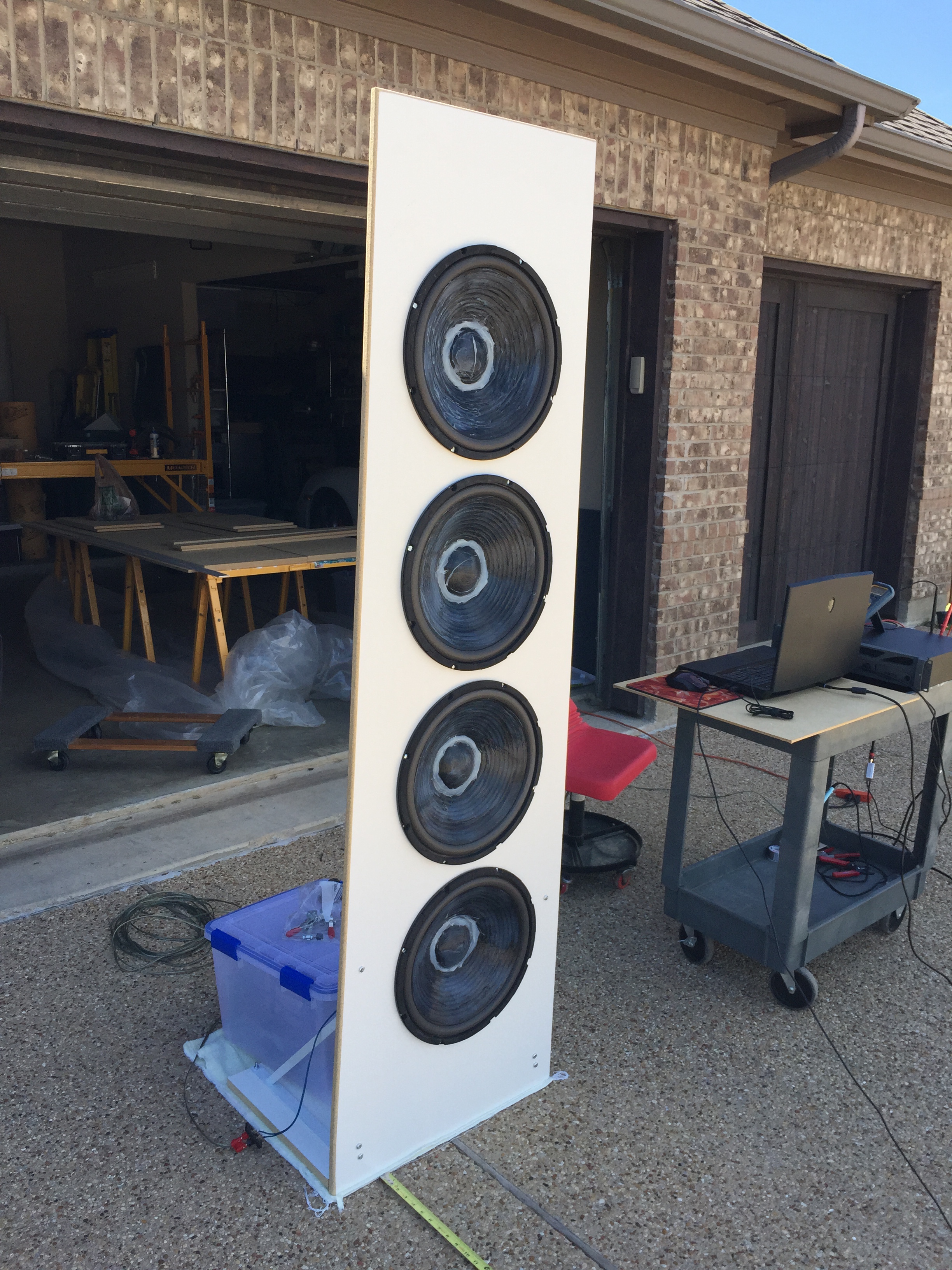
Up first is a 4 x 15″ driver configuration. The woofers are value priced models from Goldwood. You can see something on the cones – that is silicon that I added to them in order to lower the resonance frequency from 30 Hz down to 24 Hz. (As a side note, I would recommend using a black silicon instead of clear. The clear silicon doesn’t have a very attractive appearance.)
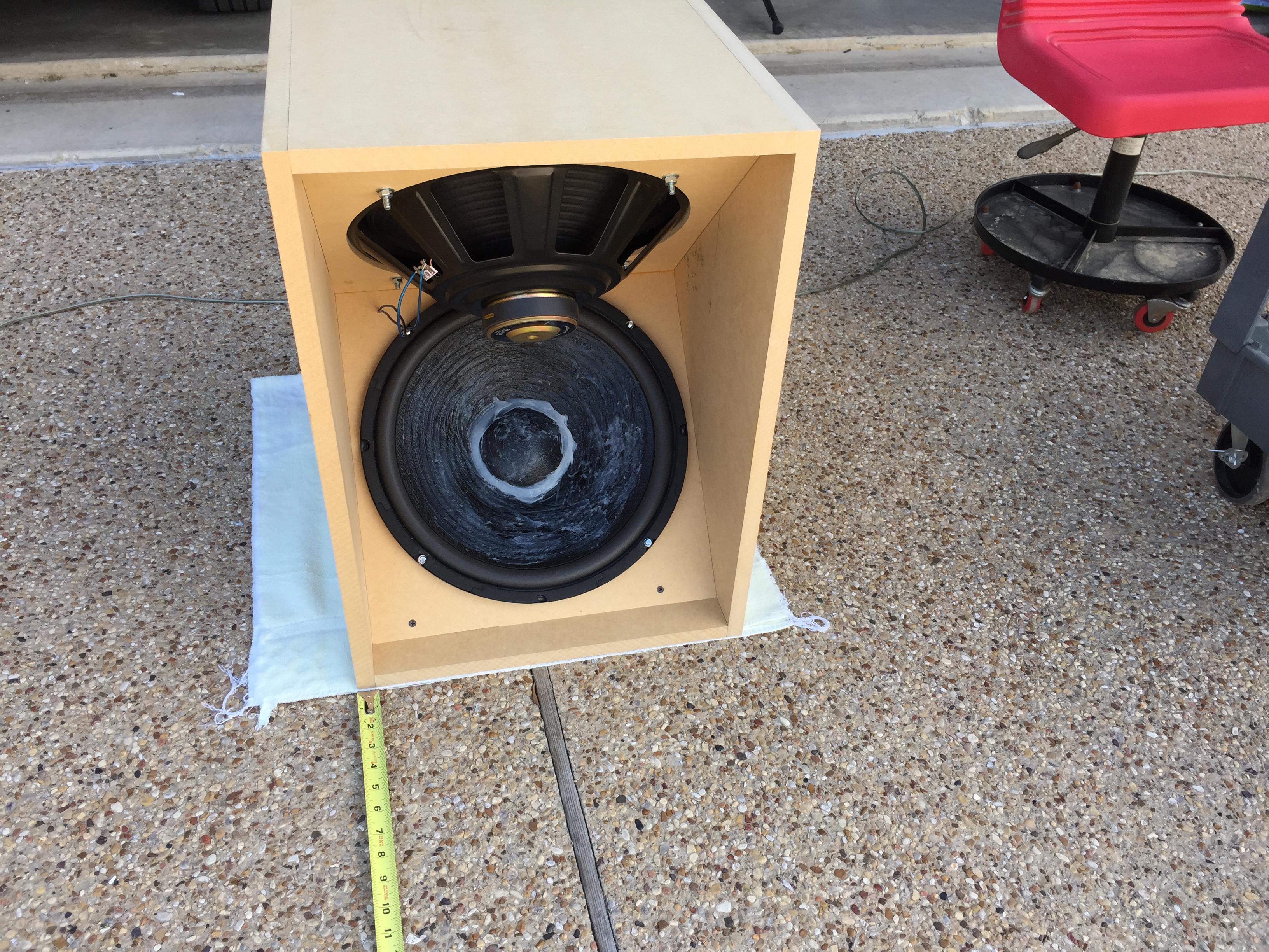
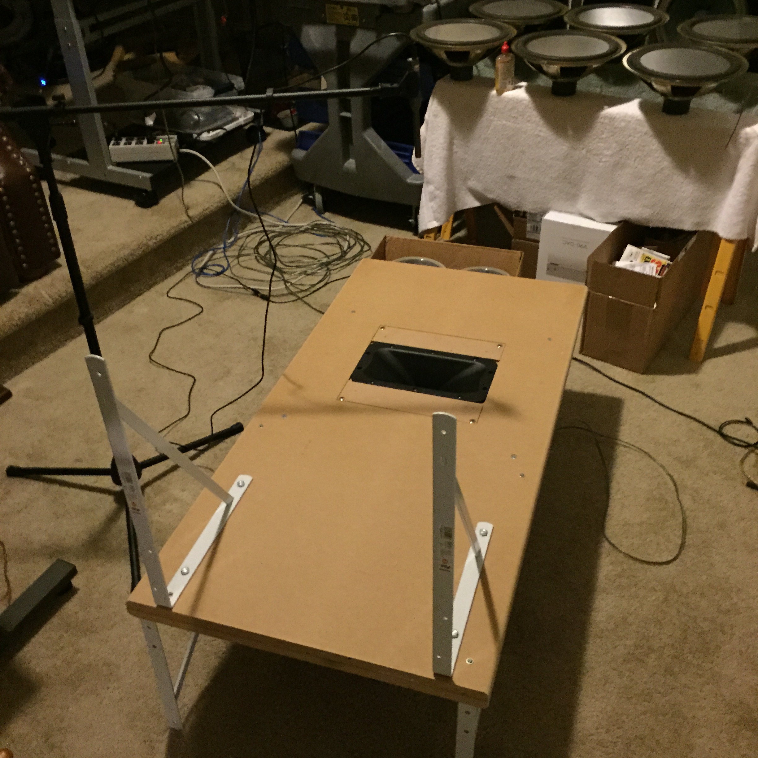
I also built an H-dipole recommended by Linkwitz. This was really easy to build, OK to move, and much stiffer than the 81″ tall panel version above.
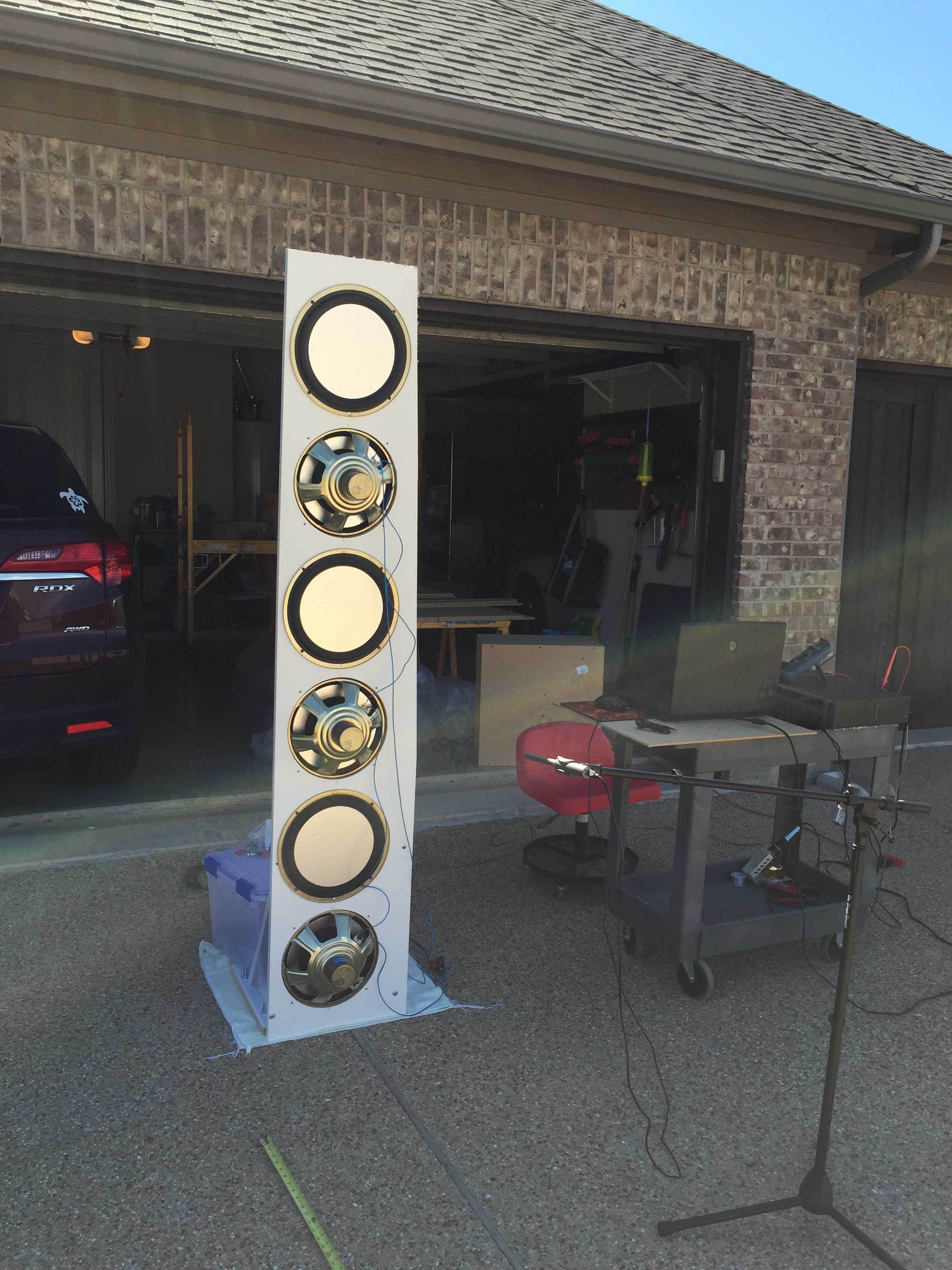
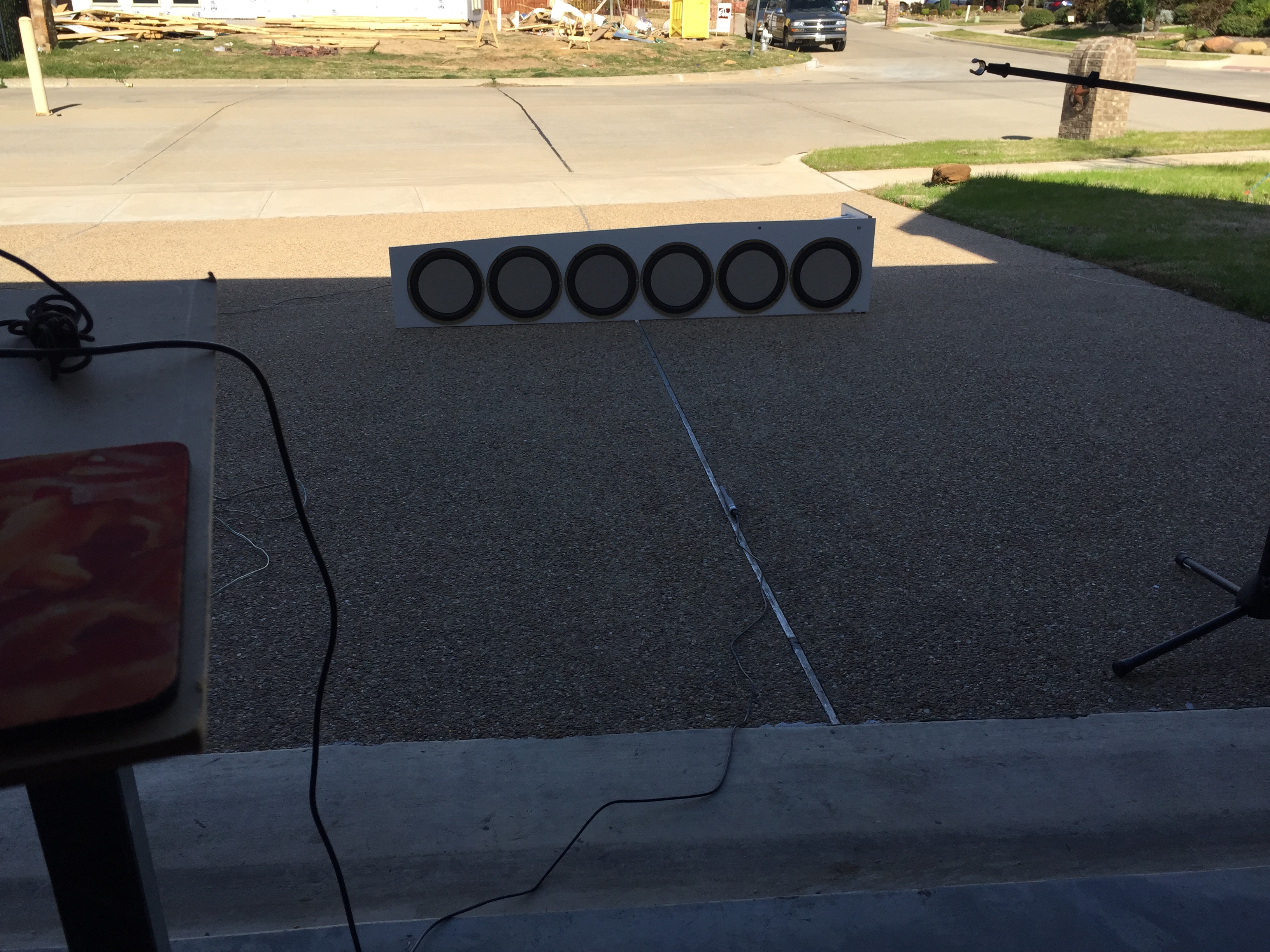
Finally, six of the 12″ carver hex woofers from the original Carver Amazing loudspeaker. Notice that half of the drivers are reversed – and connected electrically out-of-phase – so that some of the even order non-linearities would cancel out. The drivers are connected 3 in series / 2 groups in parallel. The panel is about 15″ wide at the bottom as I was not able to find the 24″ wide board that I used to make the 4 x 15″ dipoles.
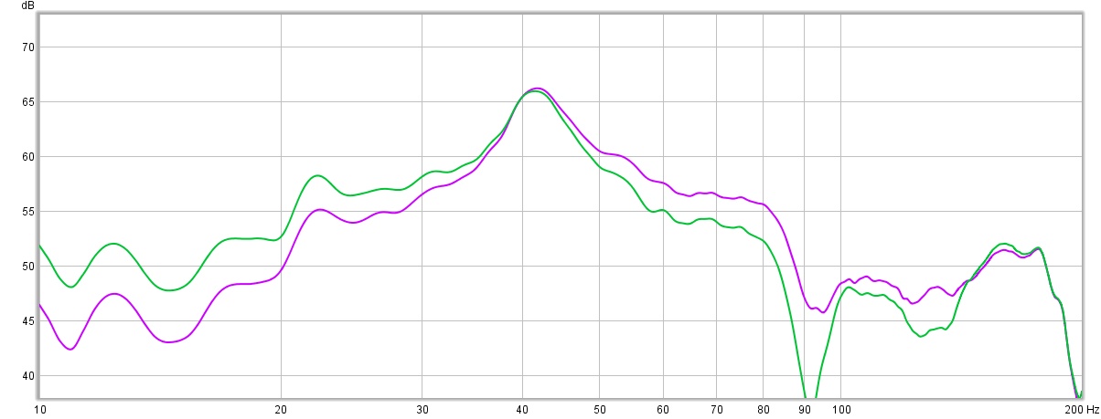
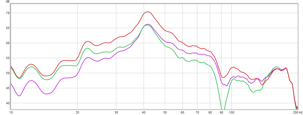
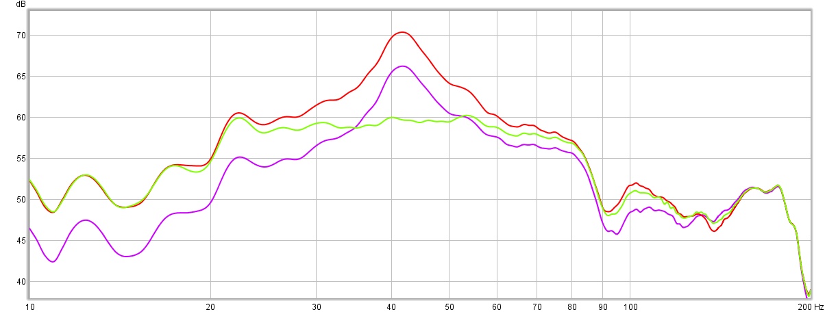
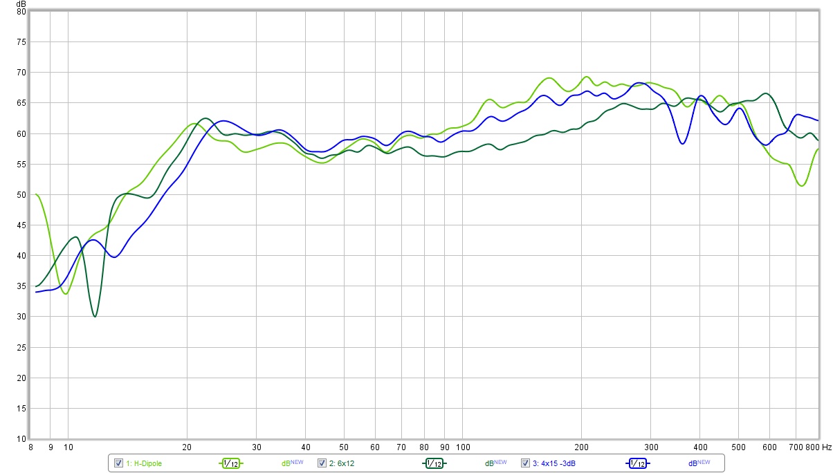
Here are some measurements adjusted to be equal in output. All measurements are smoothed by 1/24th octave filtering to help reduce the noise from the wind.
- Green = H-dipole response measured with the ground plane method at 2 meters.
- Blue = the 4×15″ dipole panel with the microphone at 1 meter, 41″ off the ground (which is the center of the 4 drivers). The level is reduced by -3 dB relative to the H-dipole.
- Red = the 6×12″ dipole panel with the microphone at 1 meter, 41″ off the ground.
I was surprised at how close the H-dipole configuration behaved compared to the panel. I was expecting the H-dipole to show more peaks and dips and otherwise be a poorer performer. Not so! In fact, I like the fact that the H-dipole forms a naturally well braced cabinet. The two panel designs both bend like a reed in the wind and flop around at low frequencies (4 Hz is especially violent).
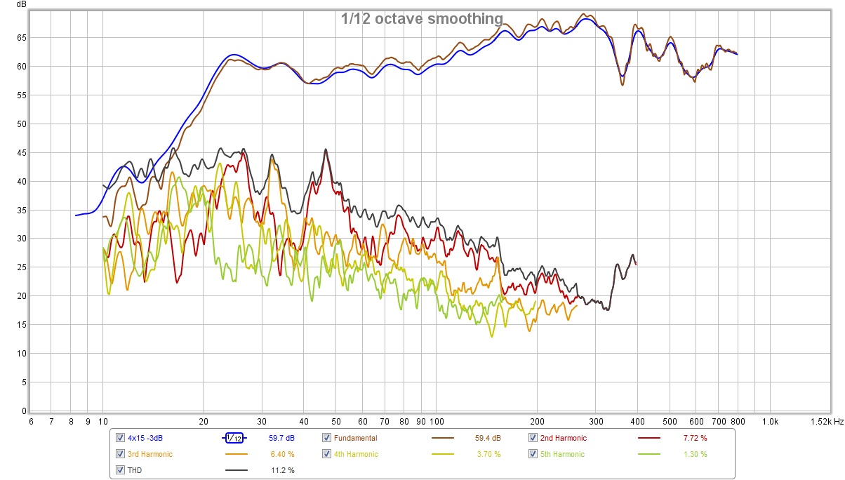
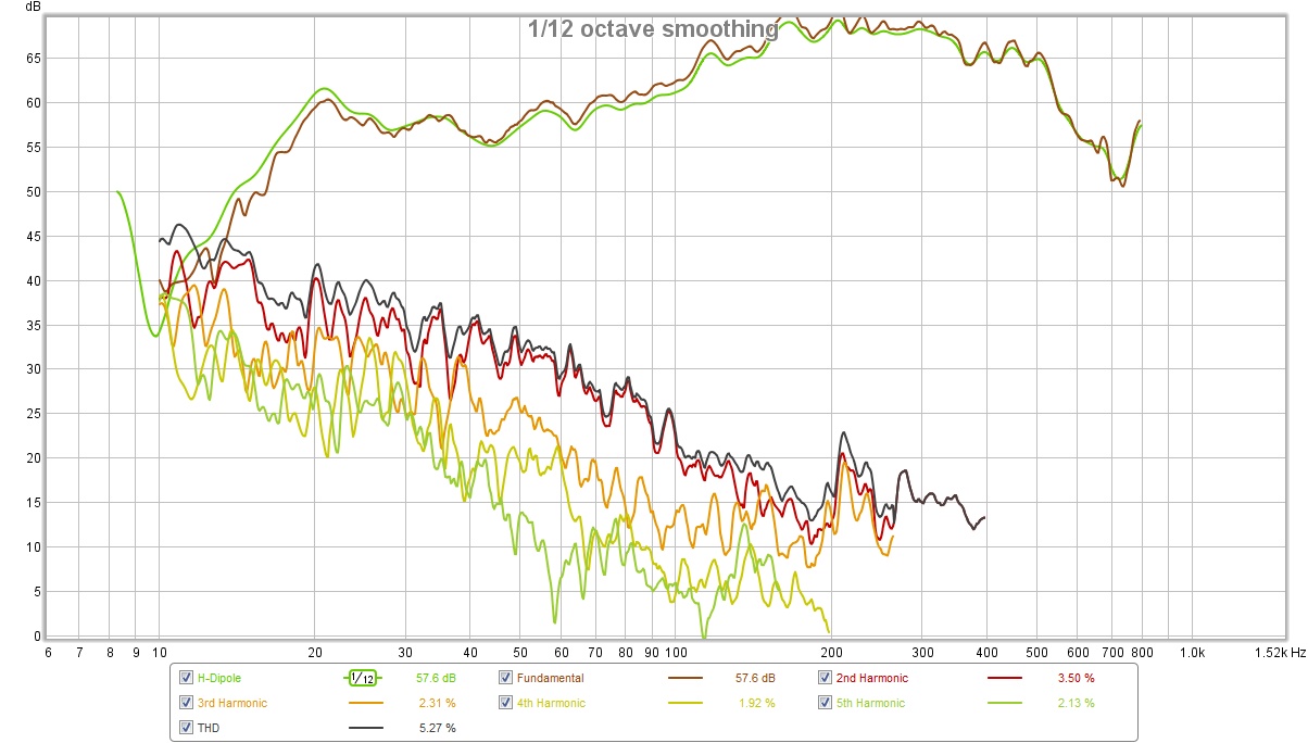
 Next up are some distortion plots. An important caveat is in order here – the wind and automotive traffic were rather problematic during testing. The plots are in the same order as introduced above. The H-dipole plot was the least windy and shows the best results.
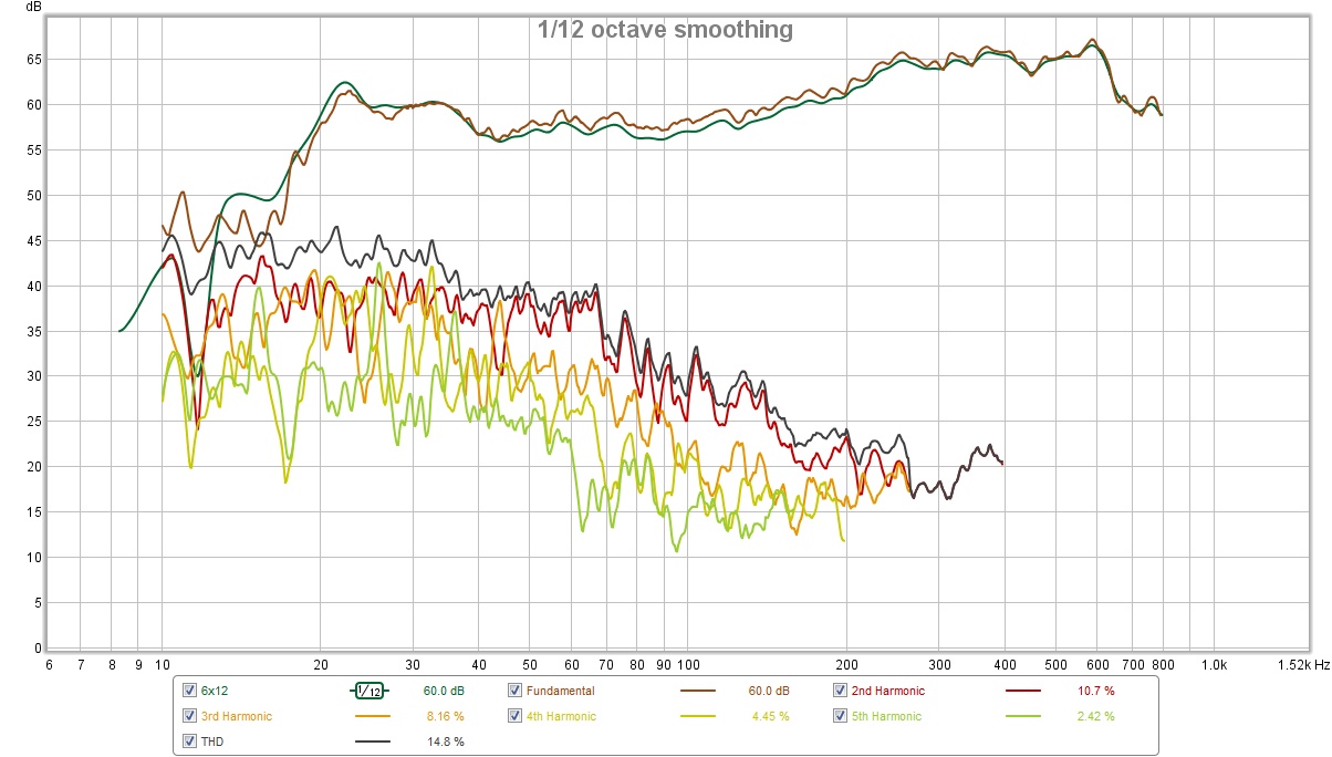 Another note is in order… the 6 x 12″ dipole panel was damaged because it fell over and cracked. Moreover, I had to swap out two of the drivers as they now buzzed. (I had just enough spares.) You can see that the panel isn’t quite straight at the top. The whole thing fell apart when I finally removed the drivers for the next prototype.
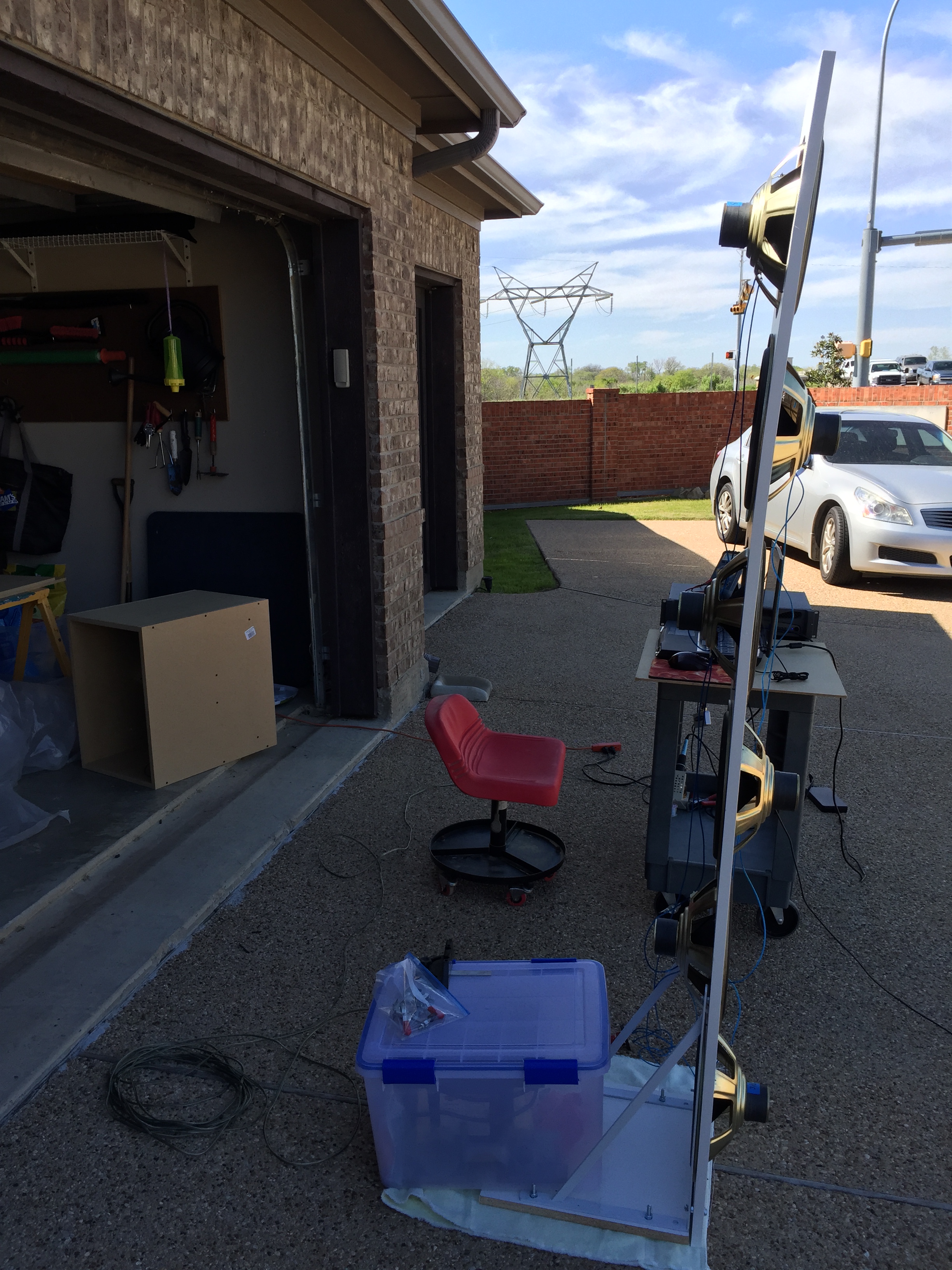
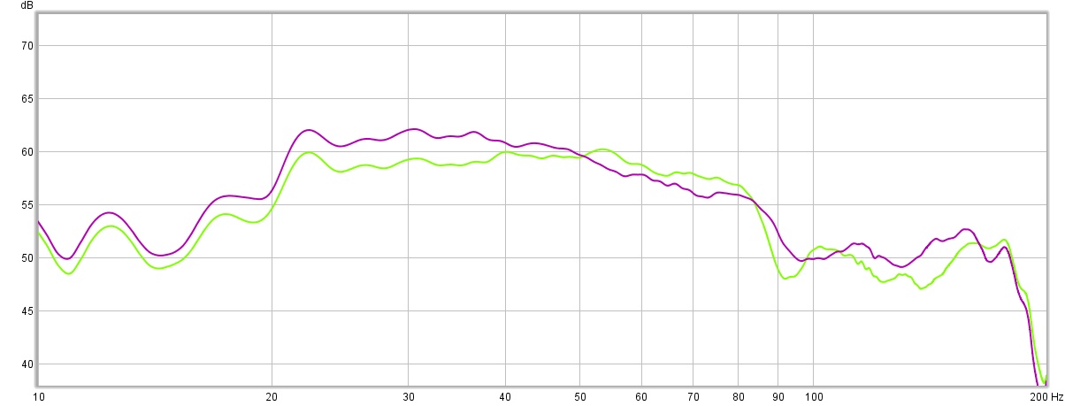
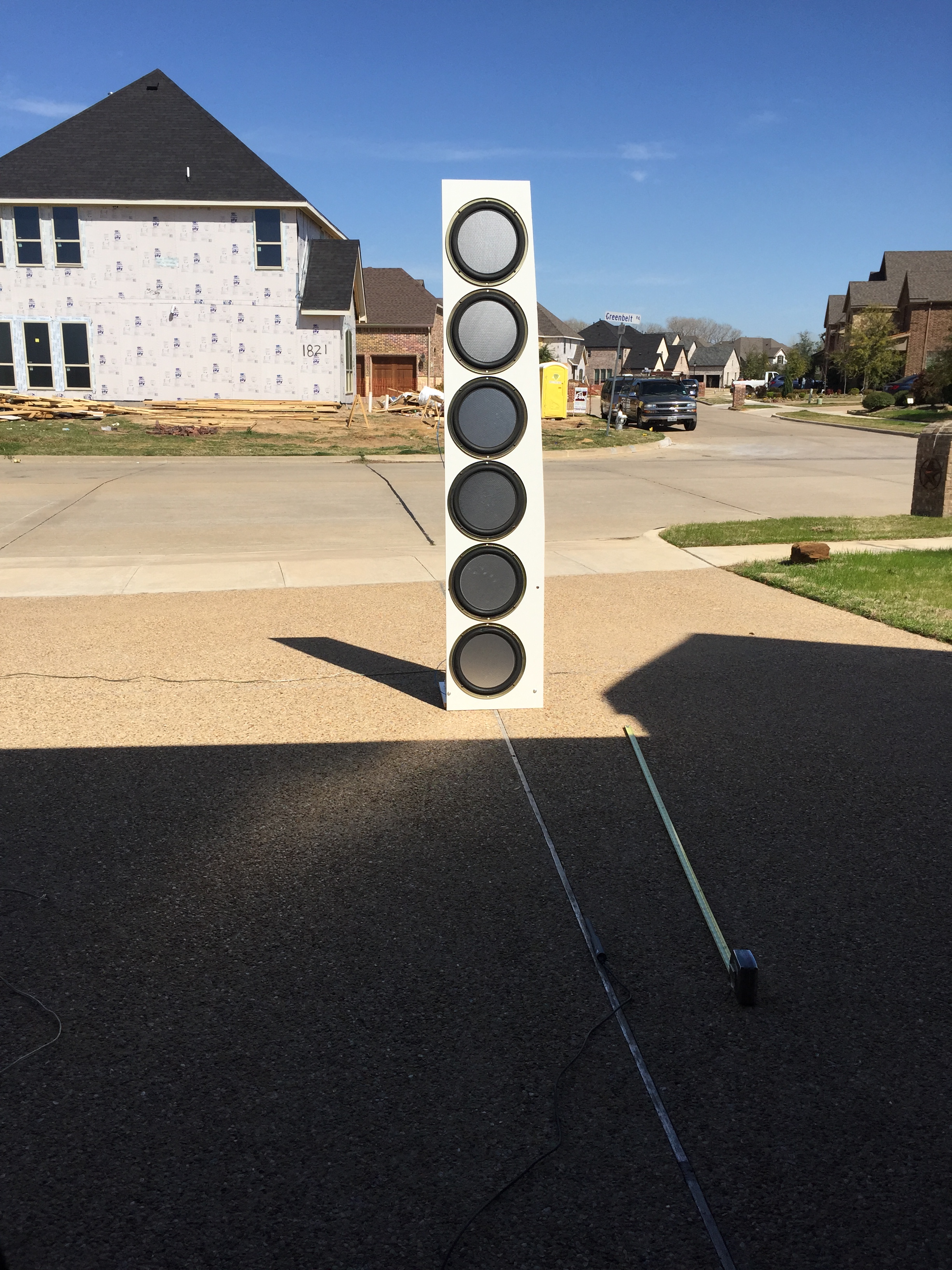 Test configuration is a ground plane measurement at 2 meters. I also did a similar measurement with the 4×15″ driver dipole panel I built with Goldwood drivers.
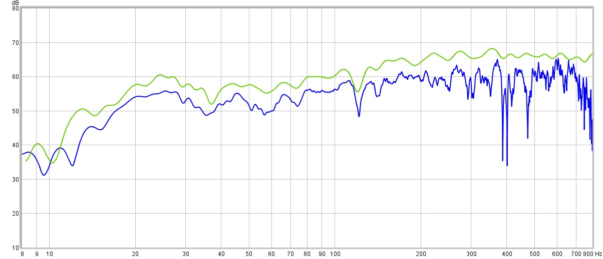
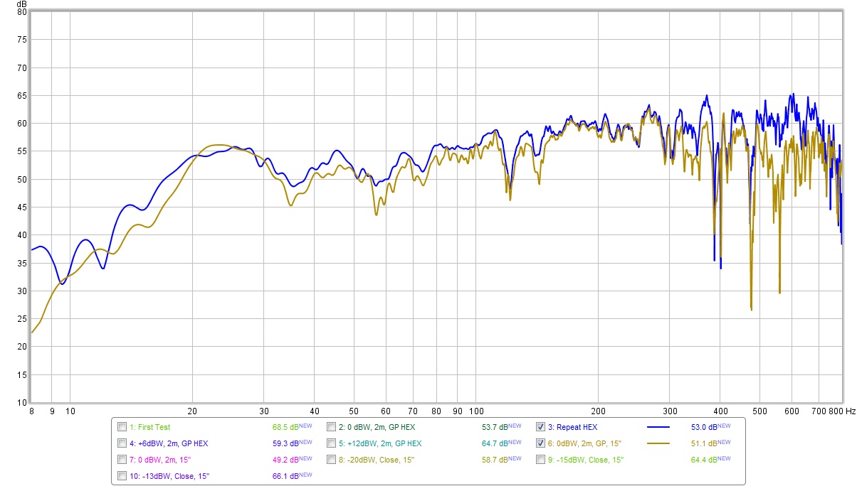 I know what you are thinking, these are the same speaker measured twice. Nope! I have added some silicon to the cones of the 15″ drivers to decrease their resonance to 24 Hz / raise their Qts to about 3.5. They are very close in specs to the original Carver drivers at 24 Hz / Qts = 3.0. Note the baffles are even different – the baffle is 24″ wide for the 4×15 and 15″ wide for the 6×12 – so maybe that compensates a little for the small difference in Qts.
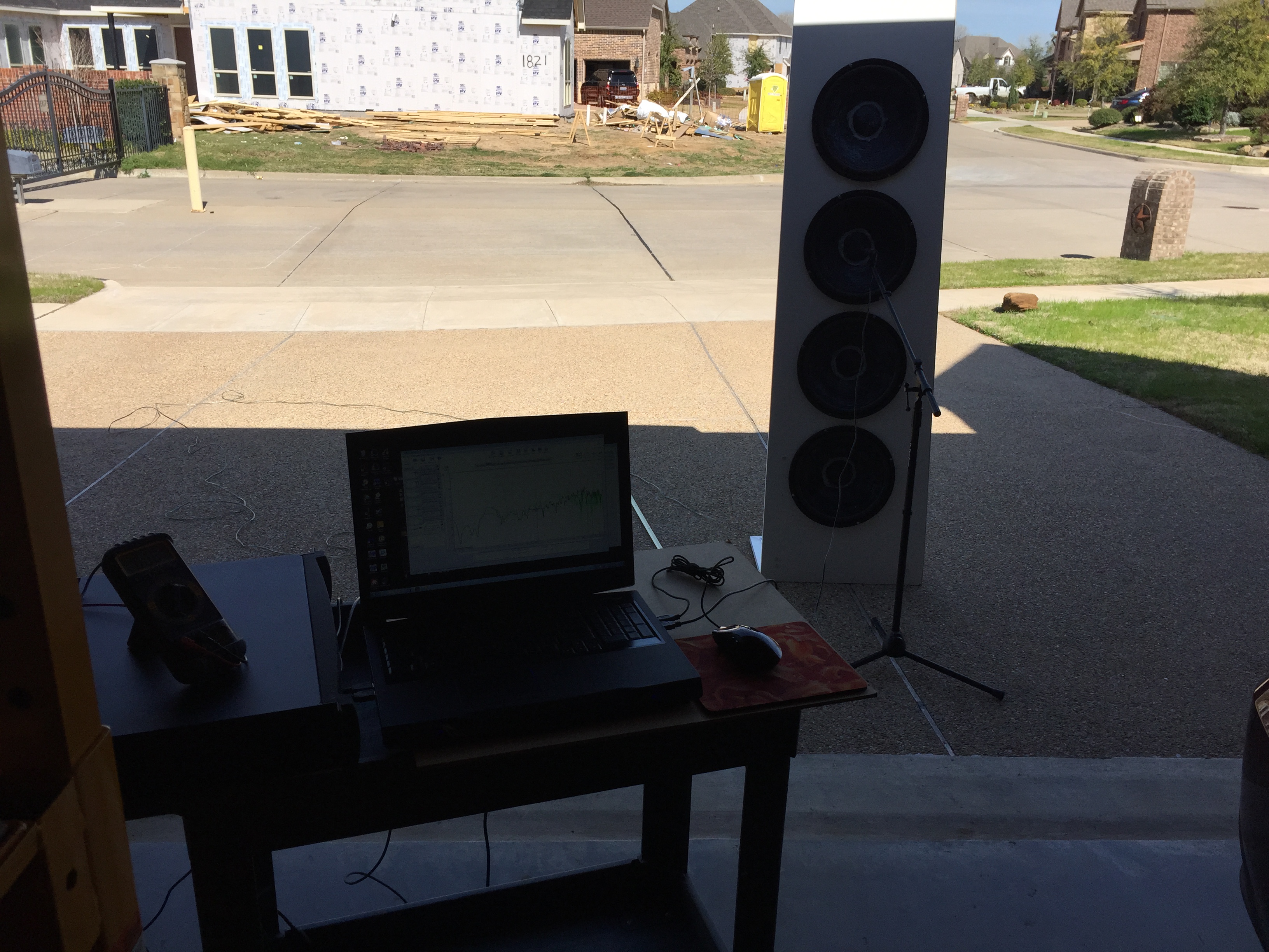
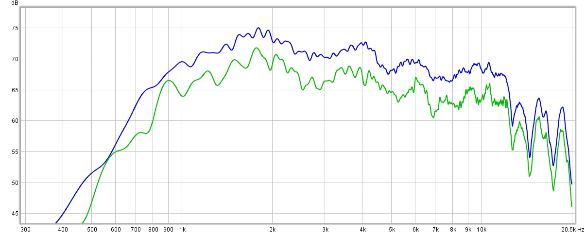
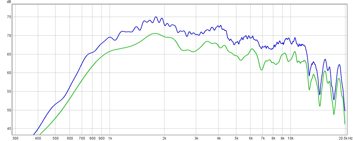
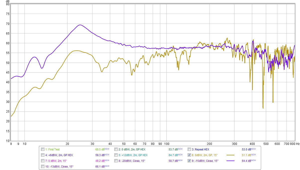 For reference, consider a close mic measurement of one of the 15″ drivers (blue) compared to the array 2 meter ground plane measurement (green). You can see that the dipole bass cancelation is -15 dB at 24 Hz. You can also see multiple dips at 35, 57, 121, and 141 Hz. I had the speakers facing into the garage, so I am wondering if these dips were due to the finite baffle, or a garage Helmholtz resonance.
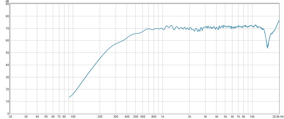
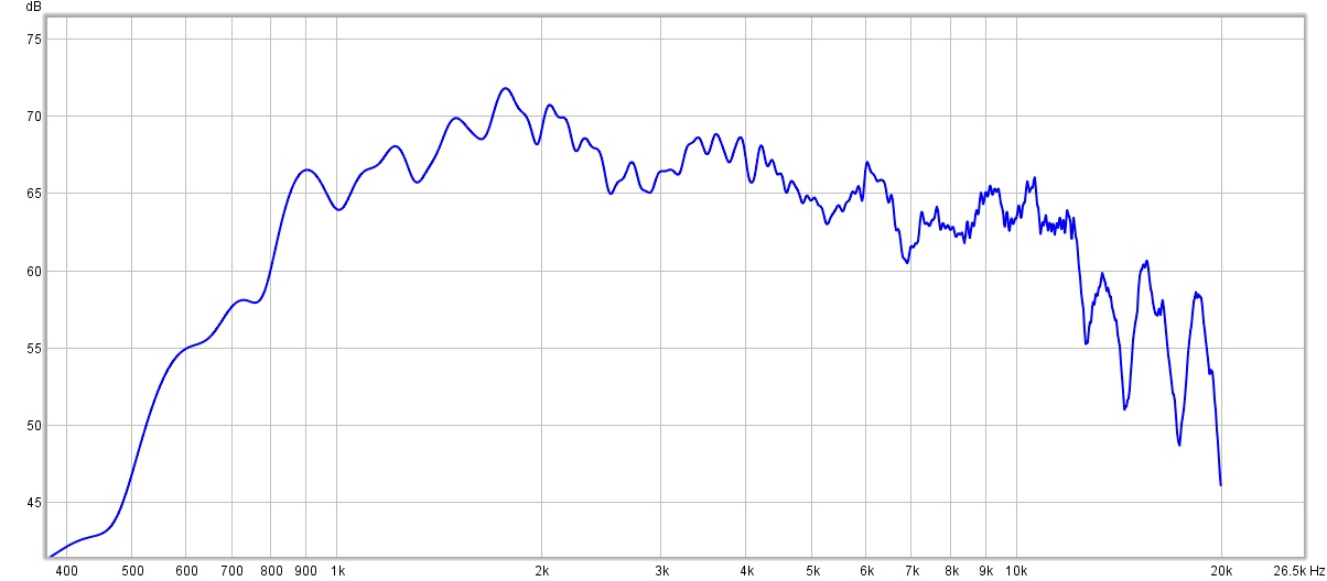
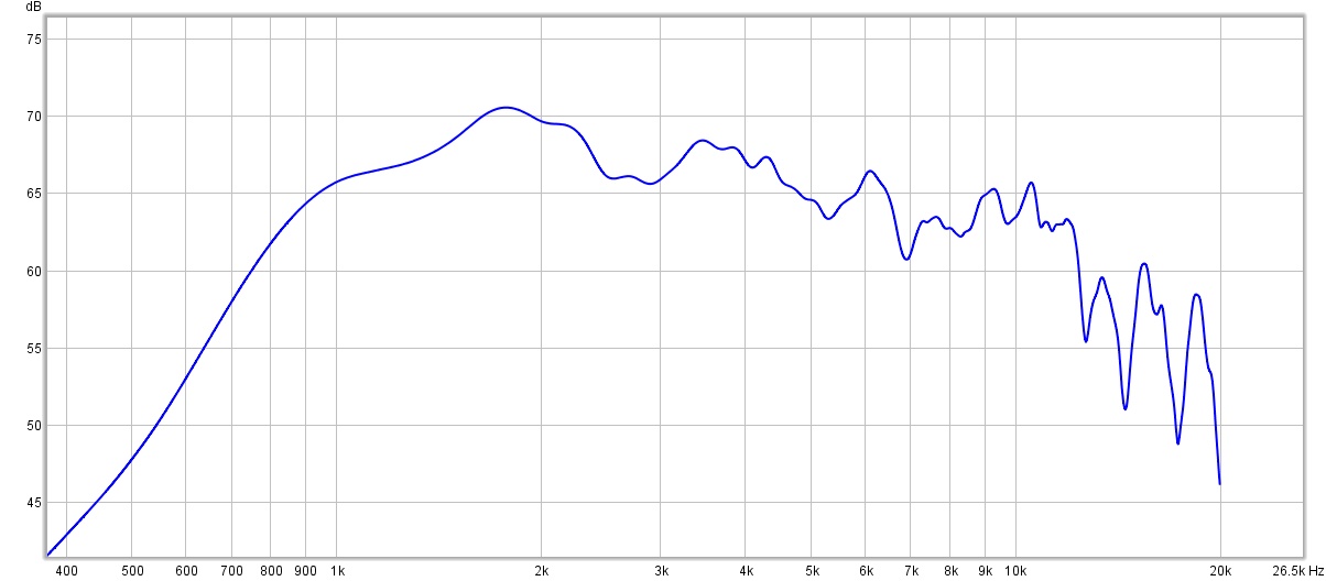
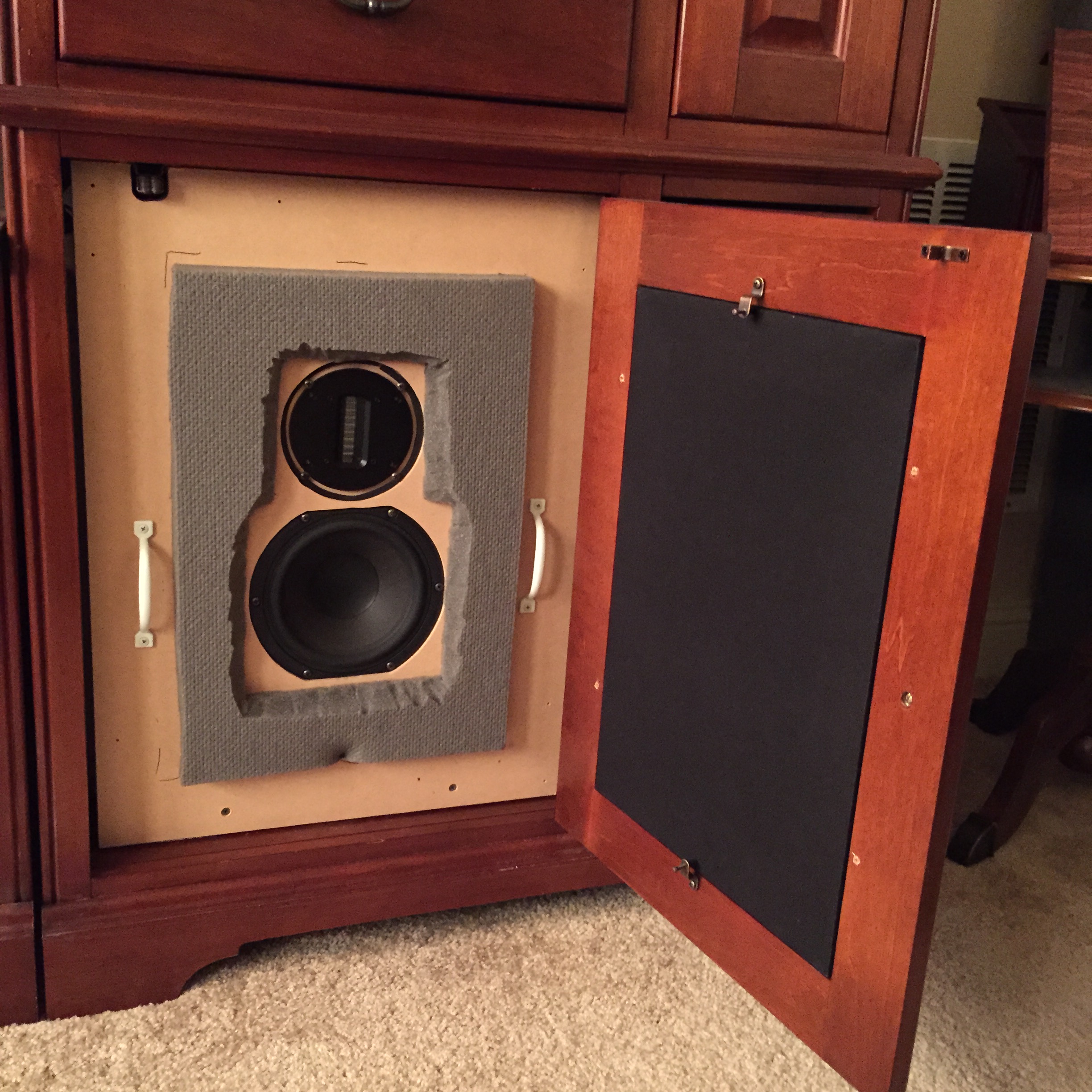 Drivers are a 2″ G2Si ribbon tweeter and Peerless 6.5″ HDS series mid-bass. Cross-over is acoustic 4th order LR at 2.5 kHz. The mid-bass is in a sealed cabinet tuned to 80 Hz. Why so high? The intention is for these to be crossed over to a subwoofer at 80 Hz as “small” speakers.
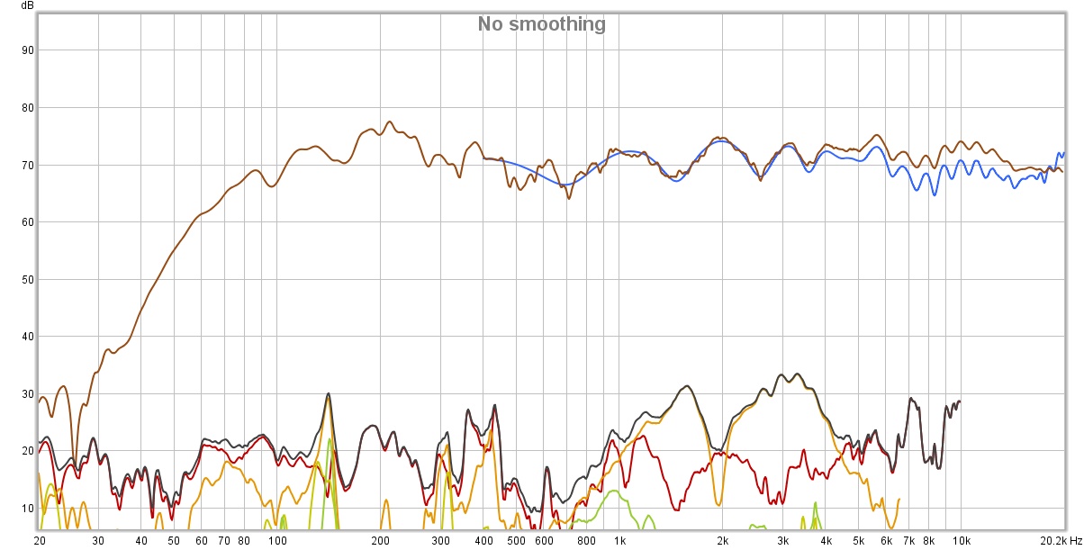
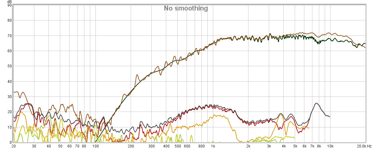
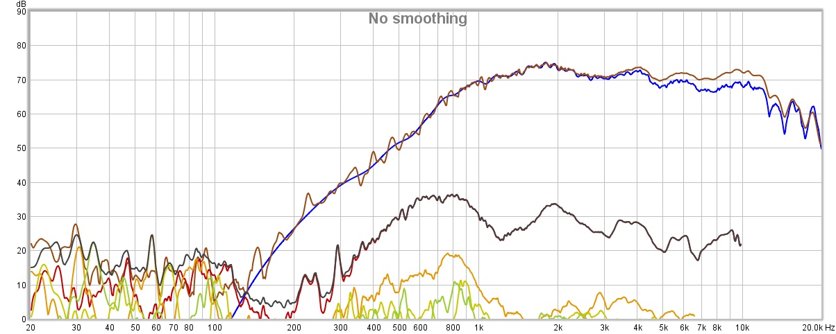
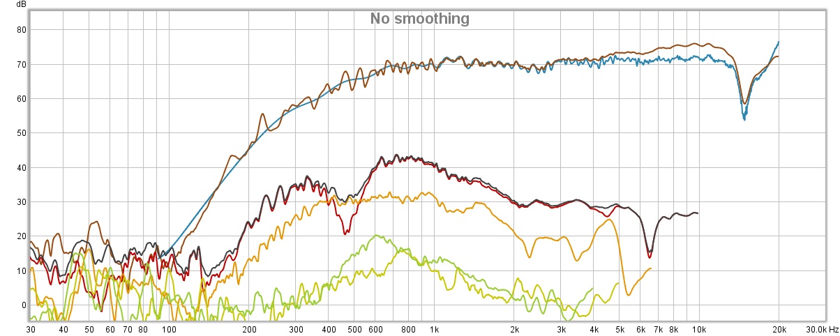
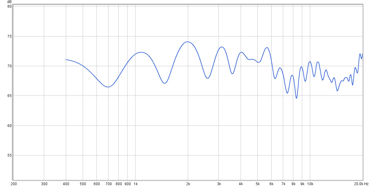 The distortion levels are respectable. The distortion above 1 kHz is mostly 3rd harmonic (green) which suggests the ribbon tweeters would sound best crossed over above 4 kHz, as well as the mid-bass could be crossed over lower as part of a 3-way design. (Will have to confirm with additional measurements of the individual drivers.) Alas, not a big enough opening in the entertainment center for 3 drivers.
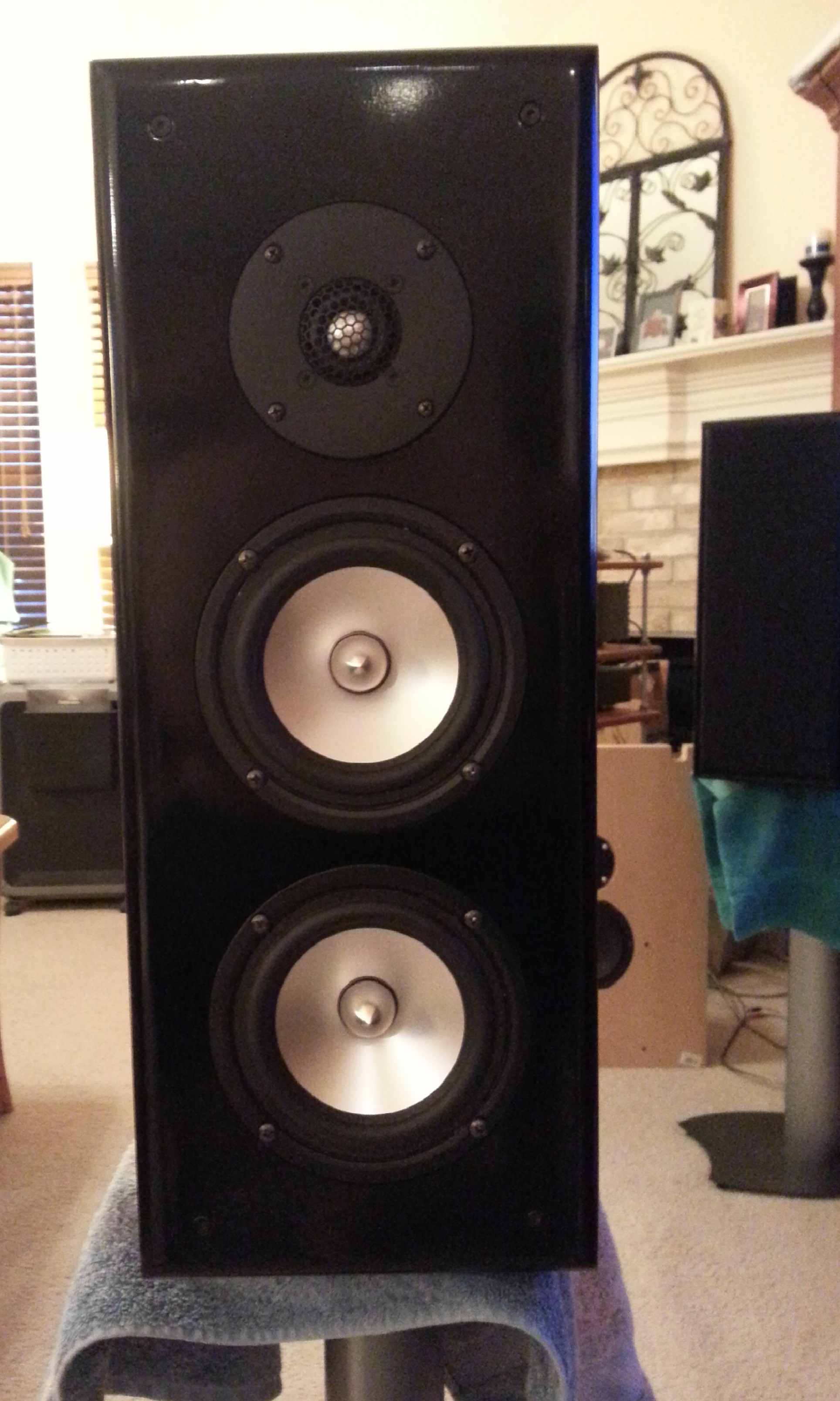
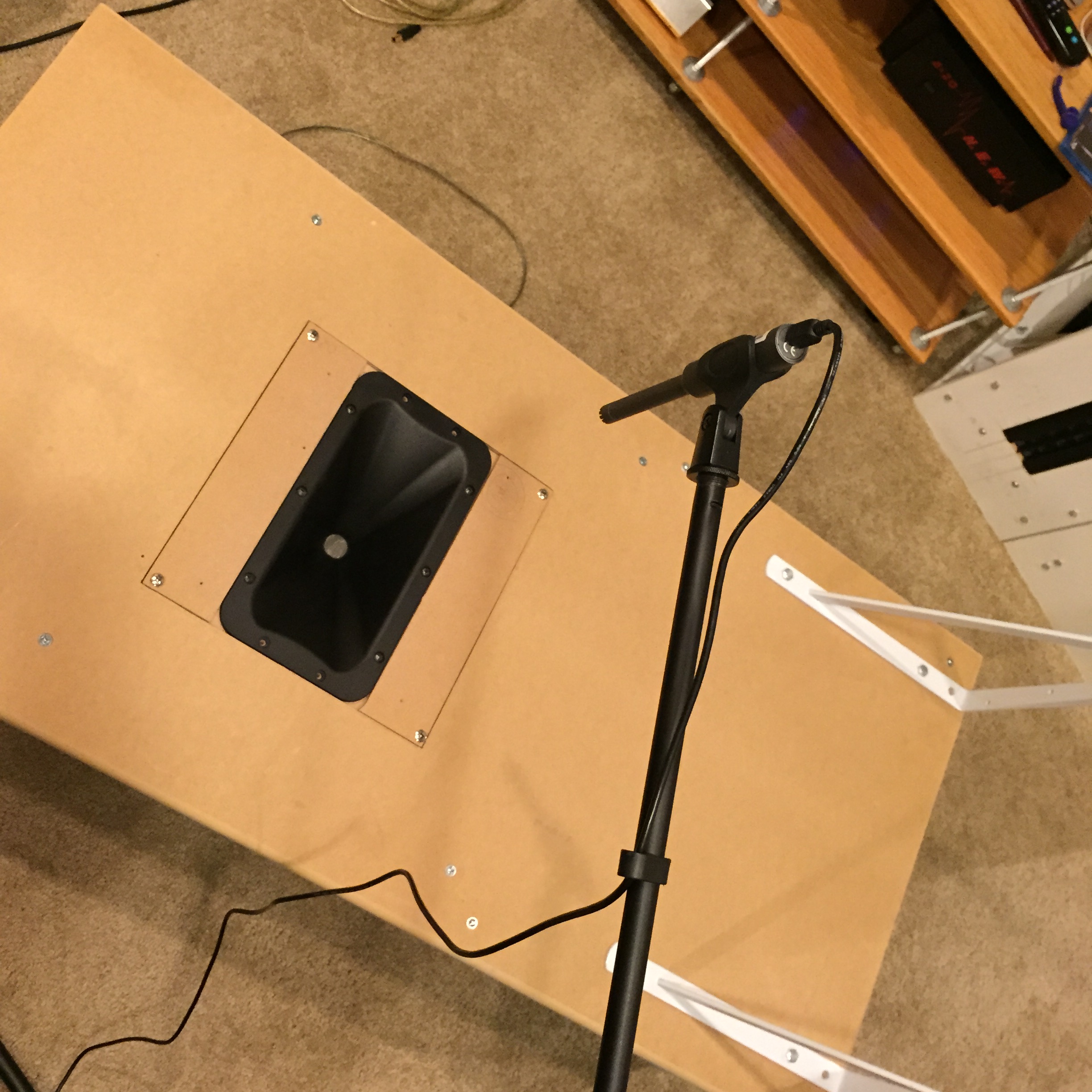
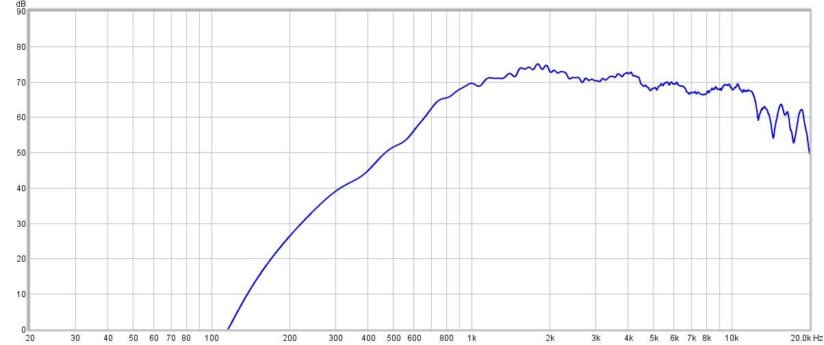
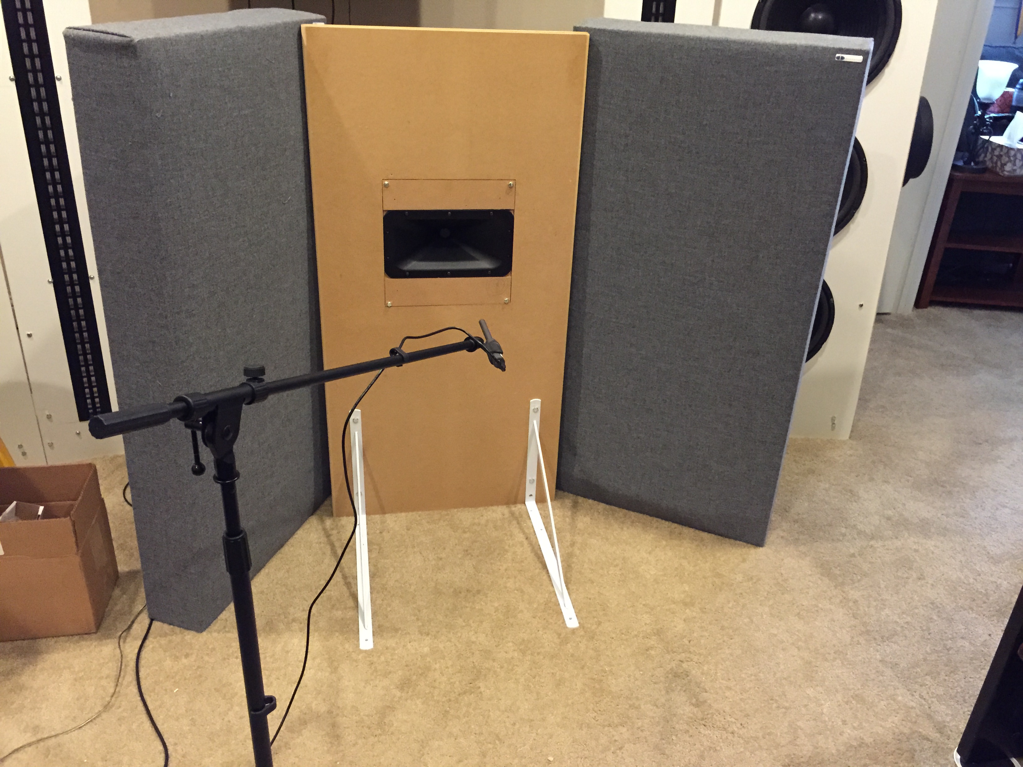


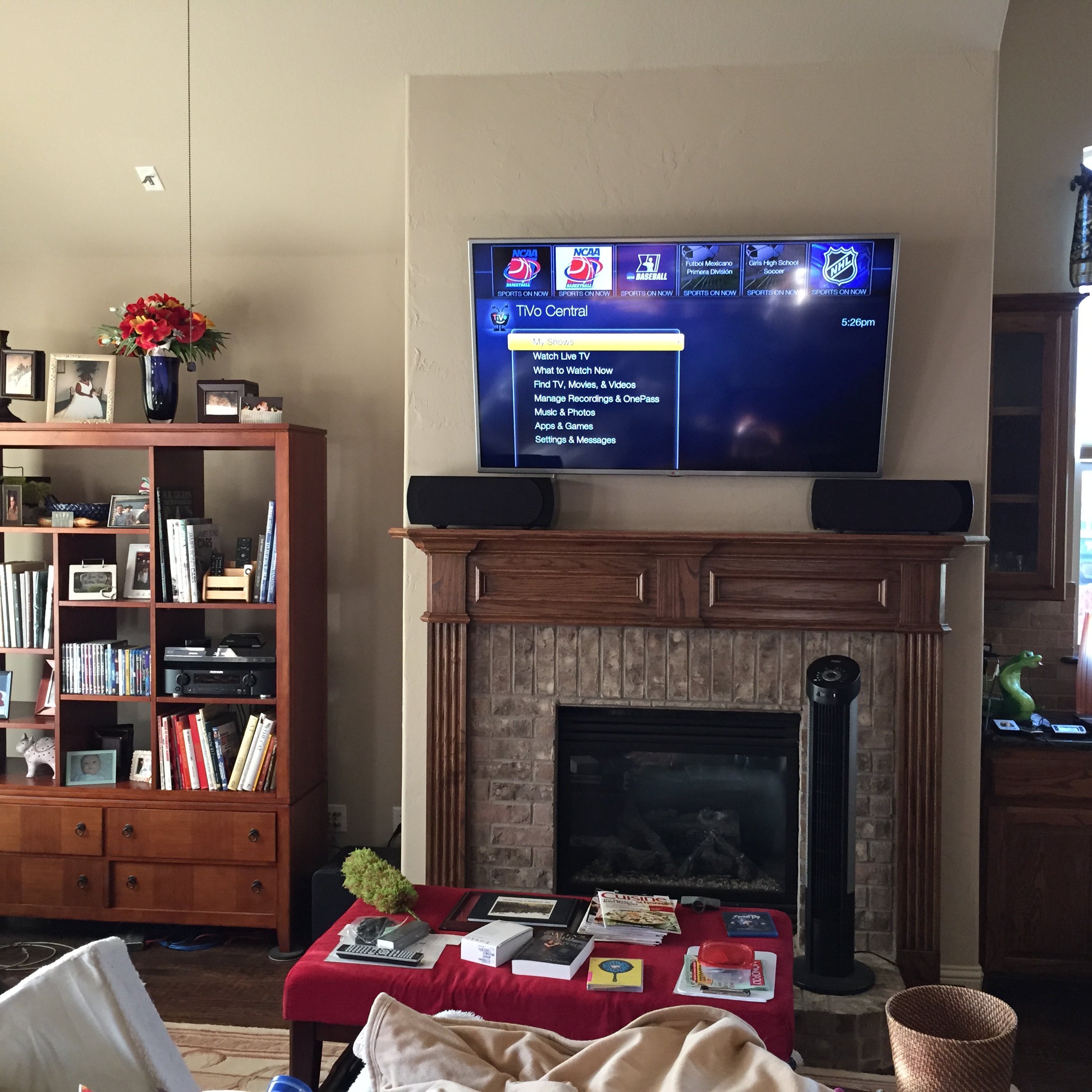 Yes, you read right. I’m using a true center channel for a left and right speaker. Here’s my reasoning. The TV in the living room is above the fireplace, leaving just less than 8″ of height for speakers below it. I looked at several loudspeaker bars and really did not like most of them. The crossovers are too high, and the mid-bass units too small to really go down to 80 Hz. Not all, just the vast majority. The few audiophile quality designs I liked were quite pricey.
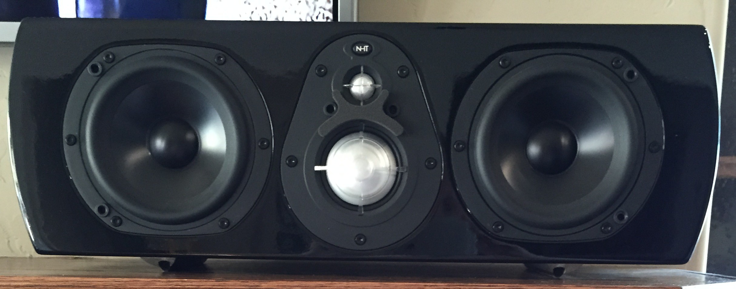
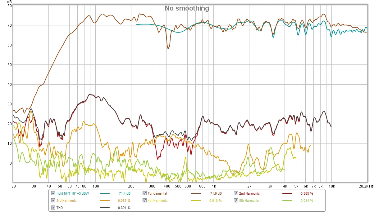
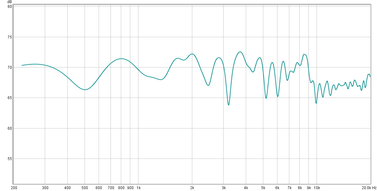 What I am really happy with is the distortion levels at 90 dB. 0.4% or less at frequencies over 1 kHz. Distortion falls to 0.2% between 300 – 800 Hz. This is excellent, beating anything else I own or have built !!! Distortion is also mostly second order, the nice distortion, except the 300 – 800 Hz range, where the third harmonic rises.
 The sound is very detailed, even with cable TV. Vocals are so clear. I watched the movie The Man from Uncle and was blown away. This movie has several parts where the movie plays music – just an amazing, immersive experience. I attribute this sound quality to the very even distortion characteristics.